Chapter 9.5 Assembling and Testing The Roll Motor
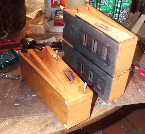
The three motor segments are assembled with long screws. There is no gasket between them; just a wooden spacer plate. The pouch leather on the sides of the motor blocks serves as the gasket. This traditionally troublesome joint can not be tightened later without taking the whole motor apart, so these joint faces are liberally spread with Dow 111 silicon vacuum grease. Later, the screw head access holes in the end blocks are covered with a circle of pouch leather, since the screw borings are close to the insides of the pneumatics, and there is a slight leakage through the porous mahogany, from inside the front pneumatic.

The gasketed blocks between the ends of the motor and the sides of the box are screwed on, with Dow 111. Then the sides of the box are attached likewise, and the top and bottom of the box are temporarily fitted, to make sure that the built-up width of the motor matches the inside width of the box.
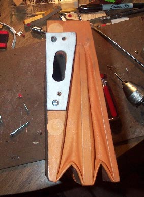
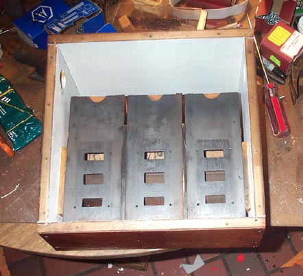
The crankshaft is cleaned up with Naval Jelly and steel wool. The connecting rod and its flange are connected with new center pins. The connecting rods are slid onto the crankshaft, and the valve wires inserted into their bushed holes in the connecting rod. The "con rod bearing" bushed hole is sawn through crosswise, and fitted with an adjusting screw to adjust the bearing diameter, This is tightened just enough so that the connecting rods swing freely around the crankshaft by their own weight, but there is no slop. The tiny flanges that connect the valve wires to the valves are installed with new piano center pins. All these bushed bearings are reamed such that the moving parts move freely; a good test is if one of the moving parts swings down by gravity while the other part is held in any position.
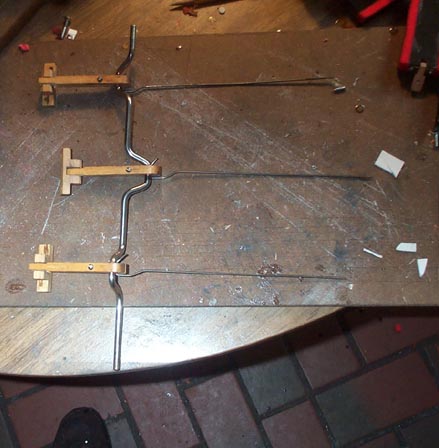
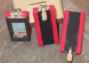
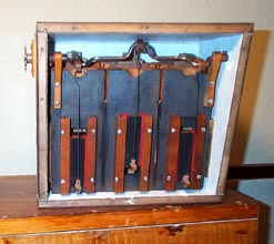
Now all the moving parts, including the floating seal (chapter 9.1) and the sprocket, are assembled. Everything should turn freely. With the motor lying flat, turn the pinion and watch the valves go up and down. Bend the valve wires so that the valves travel along the center line of the motors of their own accord. The valve guides should not have to push on the sides of the valves to keep them moving straight.
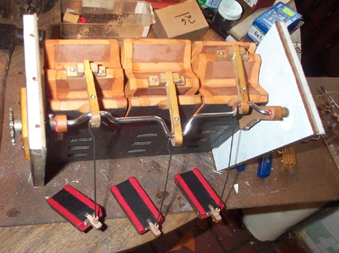
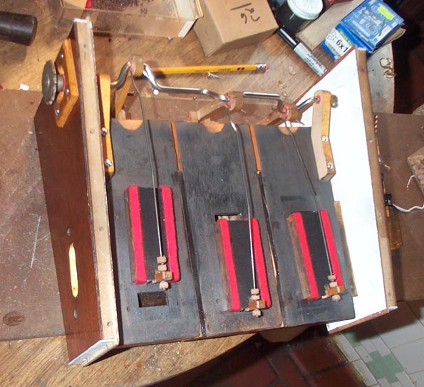
On a double acting motor, there is no way to optimize the motor performance by adjusting the valve position vertically with the leather nuts. One must depend on the manufacturer having made the valve ports and the inside of the valves with the correct dimensions. But it is vital that the valves are centered vertically over the ports; that is, that the upper and lower ports are uncovered by an equal amount as the motor turns. This adjustment is most easily made with the valve guide rails still off. A piece of tape is carefully marked at the upper edge of the upper port, and the lower edge of the lower port. Then the valves are run up and down, and their upper and lower maximum travel is marked on the tape. The nuts are adjusted until the distances between the port edge marks and the movement extreme marks are the same, top and bottom. It is important to do this carefully now, since the motor runs inside a box, and the leather nuts are not accessible for adjustment during operation.
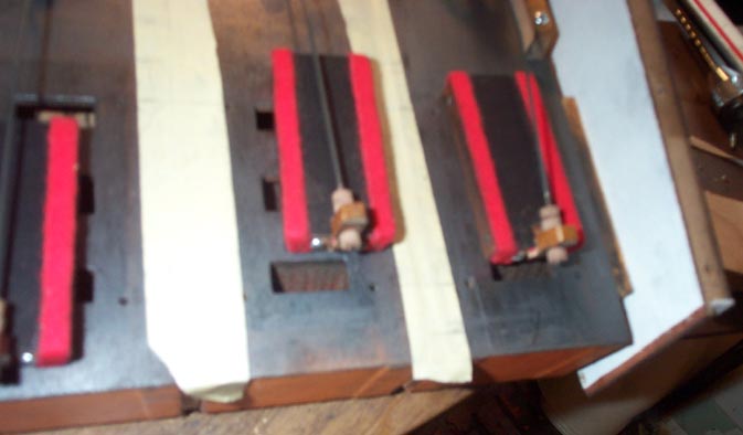
The valve guides are attached, and the rest of the box is assembled. For a preliminary test, plug the "vacuum" ports, and try to turn the motor backwards. Considerable resistance to turning is felt. With a cloth covered player piano motor, it stops dead under this test, and can hardly be turned at all. Since this motor is covered with pouch leather which is naturally porous, it will turn backwards, but very slowly when turned hard. If the motor is held in a position where the valves hang away from their seating surfaces, tiny clicks are heard when the motor is very gently turned backwards. That is the noise of the valves being sucked onto their mating surfaces. This shows that the bushed joints in the valve system are free to move easily.
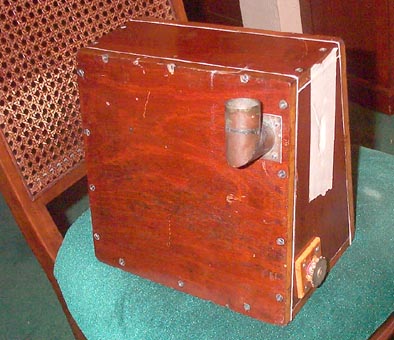
Since the player was removed form the organ in the past, the tempo valve was lost. I will have to make a new one once the organ is assembled far enough so I can figure out where it goes, and what shape it should be. For testing the motor in the organ, a temporary tempo valve was made with two hose flanges screwed together with felt gaskets. A tapered fiber piece went between these flanges, and could be pulled in and out to vary the flow.
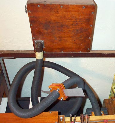
From the sprockets and gears in the transmission, I calculated that 158 RPM equaled tempo 100. Using a stopwatch, I timed various tempo settings. These were marked on the fiber wedge. Using that, I will be able to get a rough idea of the various port areas versus tempo settings for my new tempo valve.