Chapter 14.4 - Installing the Stopboard
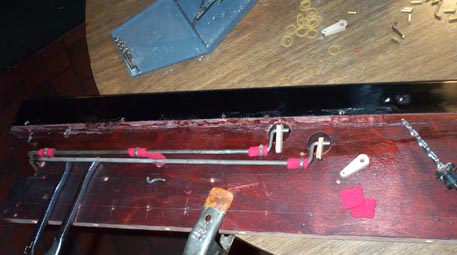
Unfortunately not many pictures here; the final assembly was pretty self evident, once all the preparations were done. But there are a few points of interest. There are two rollers on each side, to carry the motion of the mechanical stop toggles to the ends of the stop board. The rollers turn in the Aeolian patent "question mark" bushing holders, the same as described before. New toggle links were made, using the old, split ones as a template. New pallet rocker pins were made from 1/8" brass rod, to replace the old rusted ones. New cross pins for the stop rod ends of the toggle links were made.

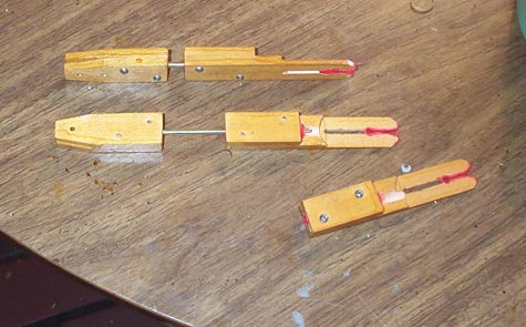
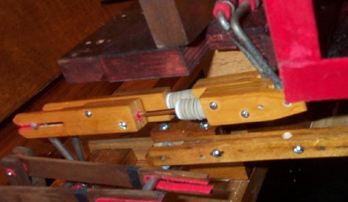
The connecting link between the rollers on the stop board, and the matching, long rollers on the keybed, was lost, so I had to make new ones. The end of the stopboard roller lever had the tee pin configuration, as I described in the keybed section. This meant that the connection there was the split and drilled wooden link end used throughout the organ. But the lever end on the keybed roller had a shoulder rivet on one side of the flattened bar end. This suggested the Estey clip-on stop roller link connection. Another problem is that this link must be sliding, or variable length. If the stop knob actuates this roller, the keybed roller must move forward. But if the Tonal knee lever is moved outward, this keybed roller also moves forward, without changing the position of the stopboard roller or the stop knob. This is what I ended up with; a link bar with a wooded screw buckle at one end, and a clip-on connection for the rivet at the other. A piece of brass rod connected to one end, and running in a loosely bushed hole in the other end, allows the link to get longer if the tonal is actuated while that stop knob is still closed. The second picture shows the link installed, and in the extended position. The closed position length is adjusted by adding center pin shim punchings.
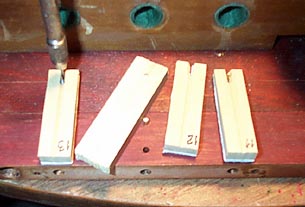
The valves are aligned on the centerlines, and new holes for the guide pins are bored with a bit of pointed wire in a pin vice. Piano center pins make perfect stem guides. A scrap of wood with a 1/16" hole makes sure that the new pins are driven in vertically, all to the same depth. Because of variations in my hand honed pallets, they are not interchangeable, so they are numbered where they go.
The original guide "staples" were rusted and pitted, and would not run smoothly in their grooves. New ones were made from 1/8" brass rod, McMaster-Carr item 8859K53, 10 one foot pieces to a bundle. These were first annealed by laying them across the big element in the electric stove, and leaving them on "high" until they had turned red, blue, and back to pale yellow. To make sure they all were the same size, perfectly straight in the middle, and had their legs all at the same angle, a bending rig was made, using an original staple as a guide. Two pieces of 3/4" aluminum bar, and one piece of 1/2", were riveted together as shown. The bar stock was clamped into the long groove in a vice, using another scrap of the rod in the groove to hold the stock in place. Then the ends were bent over with a hammer. The legs were clipped to length, and the tips slightly pointed with the belt sander. Two of the staples have one leg bent out, flattened, and drilled for a screw, rather than being driven into holes in the stop rod. These are for where the groove for the stop rod toggle would interfere with the staple leg.
The staples are installed by squeezing them into their holes with a Channelok, rather than by hammering, for fear of breaking something.
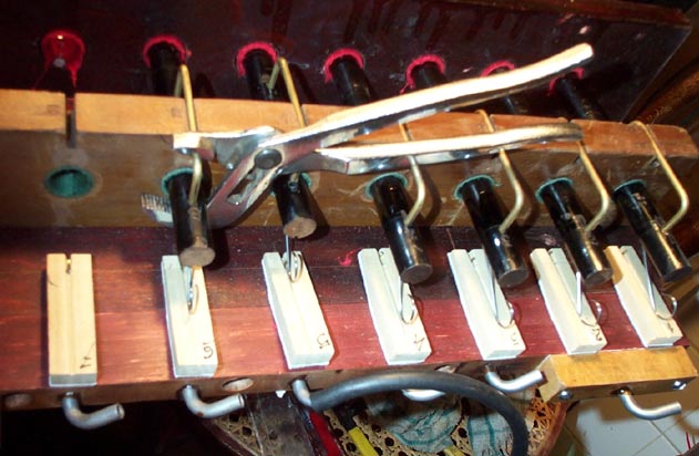
This picture also shows the new tubing elbows installed. Three groups of stops all actuate only one pneumatic primary each: The 16' "Contra Bass" and "Sub Bass" both open the pallet admitting wind to the bass chest. Another hole under the "Sub Bass" pallet, elbowed from below where you can't see it, opens the muffler on the single 16' rank of reeds. The "Viola", "Aeolian Harp", and the "Muted Strings" trio on the bass side, and the "Violin", "Aeolian Harp", and "Muted Strings" group on the treble side, all open their respective side of the violin rank chest. The distinction among these stop groups is made mechanically. The "Aeolian Harp" stops open a mute which covers the second, Celest row of reeds in the violin chest. The "Muted Strings" stops do not close the mufflers on the violin rank; they are normally closed. Rather the "Viola" or "Violin" stop opens the mufflers, clever... These groups of pallets operating a common primary are teed together with little channeled strips of wood, which were reshellacked inside, then gasketed and glued into place. This seems to me to be an elaborate way to avoid using five brass tubing tees, but with Aeolian, you never can tell.
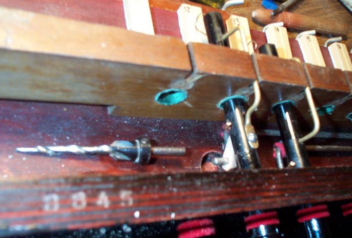
For the mechanical stops, the new toggle links were installed and adjusted for smooth action. A tapered drill, made for starting screws, is far better than a common reamer, to adjust the diameter of little holes so they fit just so. Reed organ people will appreciate the difficulties involved with getting the pins through the stop rods, to match up with the little holes in the small ends of the toggle links.
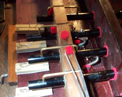
When the stop is pulled, the motion is limited by a pad of the thickest soft red felt. This has to be put on by applying a tiny drop of glue to the pad, not the board, and placing them with a tweezers. Not a bit of glue can be allowed to get on the bushing or the stop rod. Similar pads are put on the front of the rear board, to limit the closure of the stops. Due to variations, (probably my fault) different combinations of thin, medium, and thick name board felt, and medium soft red felt, had to be used to make the stops all look like they were closed to the same extent.
Now for the adjustment. The bending of the springs is very critical: too loose, and the pallets do not close reliably; too tight, and the stop binds and is hard to pull. Back when I was still trying to make the original pallets work, I tried graphite. But this did not work very well, and ended up making everything dirty, so I had to clean everything up and start over. There is something I discovered that will make the stop action smoother and lighter. The shafts of the stop rods were rough and scored, and didn't move smoothly in the bushings. Refinishing the rods struck me as a difficult and questionable enterprise, so instead I covered the front two inches and the back two inches of the rods, where they go through the bushings, with shiny transparent 2" packaging tape. The spring keeps the rod pushed up against the upper halves of the bushings, so only the top three quarters of the rods have to be taped. Impure, you say, but it floats the boat. This makes a 100% improvement in the ease with which a stop can be pulled at any given spring pressure. The guide staples have very little clearance in their grooves, and can bind, so some of the staple legs have to be bent slightly so that the staple crossbar is exactly parallel to the stop shaft.