| You Are Not Logged In | Login/Get New Account |
|
Please Log In. Accounts are free!
Logged In users are granted additional features including a more current version of the Archives and a simplified process for submitting articles. |
|
MMD
 Gallery
 Tech
Tech
 Wur125
 directions
|
|
courtesy Dana Johnson
DIRECTIONS FOR THE CARE AND OPERATION OF THE MILITARY BAND ORGAN
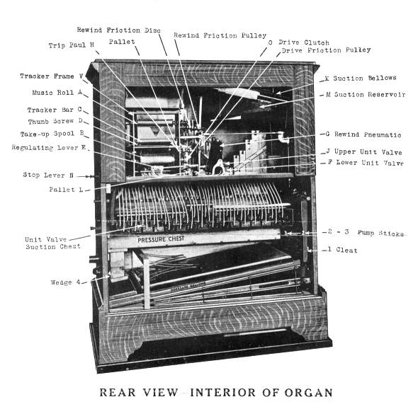
For Roller Skating purposes, the organ should be placed three or four feet above the skating surface, in order to carry the music out over the skaters. Having placed the organ in the desired position, place the countershaft in back of the organ so that the 16-inch drive wheel on the organ will line up with the 5½-inch wheel on the countershaft. Place the motor properly, and line up the 3¼-inch pulley on the motor with the 16-inch drive wheel on the countershaft. Next, cut off the suction on the organ by pulling the Stop Lever that projects on the side of the organ (to the left) as far as it will go. Start the motor, and see that it drives the organ drive wheel to the right. If it does not turn to the right, reverse the motor, or cross the driving belt to the organ. Organ should turn up about 75 or 80 revolutions per minute. Stop the motor and place the drums on the side of the organ. These will fit but one way and cannot be put on wrong. Connect the rubber tubes with the brass nipples projecting from the side of the case. Place the cymbal on top of the organ and connect rubber tube with brass nipple. TO PUT ON THE MUSIC ROLL After placing the instrument in position and connecting it with the motive power, open the small door in the rear, and put on the music roll. To put the music roll on the long tune spool, screw off the brass thumb nut on the end of the rod, slide off the flange, and place the music roll over the rod with the end containing the key on the inside of the roll to the bottom, and turn it so that it will fit into the keyway in the hub of the lower flange. Next, place the upper flange on the rod, also turning it to fit the groove in the flange. Screw on the thumb nut, allowing about 1-64-inch play between paper and flange. Place the music roll in the Tracker Frame "V," with the pointed end to the left, push toward the left, and slip the key end into the slot. Connect the end of the Music Roll with the hook in the Take-Up Spool "B." Be sure that the Stop Lever "N" at the left of the organ case is pulled out to the LEFT as far as it will go. This releases the Drive Clutch "O" so that the music and Take-Up-Spools will turn freely by hand. Turn the Take-Up Spool "B" a few revolutions to bring the perforated holes in the Music Roll "A" directly over the holes in the Tracker Bar "C." See that the holes in the Music Roll are directly over the holes in the Tracker Bar, also that the flanges on the Take-Up Spool do not double the edge of the Music Roll. Then pull the Music Roll back on its spool until you bring the blank paper over the Tracker Bar. Push the Stop Lever "N" to the RIGHT, and start your instrument. Should the flanges on the Take-Up Spool "B" be too close and curl the edges of the Music Roll, loosen the set screw in the left hand flange and set it so that it will have about one-thirty-second of an inch play between the paper and the edge of the flange, BUT NOT MORE THAN THIS. TO REGULATE THE TRACKER-BAR SHOULD THE MUSIC ROLL NOT TRACK PROPERLY Just in front of the Tracker-Bar "C," on the left-hand side of the Tracker Frame "V," will be found a Thumb Screw "D", by which the Tracker-Bar "C" can be shifted in either direction, as may be necessary to bring its holes in line with those of the Music Roll. Loosen the Wing Nut on this Thumb Screw and turn screw to the proper adjustment, and then tighten up the Wing Nut again. Care should be taken to keep the Tracker-Bar "C" free from dust, by frequently removing and blowing out. To do this, raise the small levers at each end of the Tracker-Bar, remove the brass Tracker-Bar and the small screen, blow both out clean and replace, taking care not to turn Hie edges of the screen, and to pull the levers at the end of the bar firmly back in place. TO REGULATE SPEED OF THE MUSIC, loosen the small thumb screw on the Regulating Lever "E," and move to the right for fast, and to the left for slow, as indicated on the speed regulator bracket. Tighten the thumb screw up again when the desired speed is reached. HOW THE MUSIC REWIND DEVICE WORKS When the music roll has played through and the Rewind perforation in the paper is reached, it admits air to the lower Unit Valve "F," which collapses the Rewind Pneumatic and holds it in the rewind position. When this Rewind Pneumatic closes, it pulls the ^spring on the Pallet "L" open and admits air to the Suction Cut-Off pouch located in the upper left hand corner of the organ case, which cuts off the suction from the chest. At the same time the Drive Clutch is disengaged, and the Rewind Friction Pulley engages the Rewind Disc and rewinds the music roll. When the roll is entirely rewound, the Trip Paul "H" falls into the groove in the Take-Up Spool, and pulls open a Pallet which is located just back of, and directly in line with the Trip Paul. This admits air to the upper Unit Valve "J," which cuts off the lower Unit Valve, and releases the Rewind Pneumatic into play position. At the same time the Pallet "L" closes and suction is admitted to the chest, the Friction Drive Pulley and the Driving Clutch drop into position, and the organ starts to play. TO STOP THE MUSIC INSTANTLY The Stop Lever "N" at the left of the organ case is to stop the music instantly without shutting off the current. By pulling this lever to the LEFT, it opens a Pallet leading to the Suction Cut-Off which releases the air from the chest. It also throws the Drive Clutch "0" out and stops the motion of the music roll. Always have the Stop Lever "N" pulled over to the LEFT when changing the music roll. This lever obviates the necessity of stopping the instrument. while changing the music. The Hook on the Rewind Pneumatic should not be used except for tuning. See Tuning instructions. TO REMOVE THE PRESSURE BELLOWS Should you have occasion to remove the Pressure Bellows to make repairs, proceed as follows: Loosen up the screws and remove the Cleat, No. I, on the right-hand side, take out the Pump Sticks, No. 2 and No. 3, and remove the screw in front of the Wedge, No. 4, on the left-hand side so that the wedge can be removed. When you have taken these parts out, you can easily slide the Pressure Bellows out of the organ. WHAT TO DO IF A NOTE SPEAKS CONTINUOUSLY This will happen occasionally, owing to dirt or some other obstruction lodging under the 'pallet just enough to hold it open a little. Remove the screws in the front board of the pressure chest, which gives access to the pallets. To clean the pallets, use a thin flat stick with a piece of fine sand paper glued to it, and clean them by drawing the sand paper and over the leather surface of the pallets. This will remove whatever dirt may have lodged on them. You may find, however, that the trouble is in the Suction Chest and not in the Pressure Chest. To locate the valve giving trouble proceed as follows: Either rewind or play the roll until you come to the blank space between two pieces. When this blank space is over the tracker-bar, press the Rewind Pneumatic over to the RIGHT just far enough so that you can pull the hook on the pneumatic down over the screw. This will hold the pneumatic in position so that the Drive Clutch is out, but that suction still remains on the chest. Then reach under the Suction Chest and try the stickers that run into the Pressure Chest. Pull these down one by one so that the pipes speak. When you come to one that is already down as far as it will go, and will not come back up again, that is the one that is controlled by the valve giving trouble. The valve block is located in the suction chest almost directly in line with this sticker. Take the tubes off of one or two valve blocks and try to make them repeat by tapping the finger over the end of the brass nipple. If it does not repeat, you have the valve that is causing the pipe to speak continuously. To remove the Valve Block, simply loosen up the two screws that hold it to the channel board of the chest. The block can then be removed, and the valve cleaned out. When replacing the block, be sure to pull the screws up tight with an even pressure. Do not try to pull them up too tight or you may strip the thread in the wood, and they will pull out again. The compression springs under the heads of the screws arc there to hold the blocks tight at all times and take up any space caused by drying out of the wood. NOTE We have tried to make our organs as simple in construction as possible. If there is any adjustment that you do not understand or you have any troubles that you cannot remedy, write us, and we will cheerfully forward the necessary information. THE RUDOLPH WURLITZER MFG. COMPANY,
01 April 2003 |
|
|
|
|
|
|
|
|
|
CONTACT FORM: Click HERE to write to the editor, or to post a message about Mechanical Musical Instruments to the MMD Unless otherwise noted, all opinions are those of the individual authors and may not represent those of the editors. Compilation copyright 1995-2024 by Jody Kravitz. Please read our Republication Policy before copying information from or creating links to this web site. Click HERE to contact the webmaster regarding problems with the website. |
|
|
||||||
|

