Chapter 4.8 - Assembly and Test of the Lower Unit
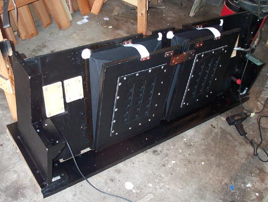
After the feeders were covered, the whole lower unit was assembled on the end support slabs, and set down on to the massive base wagon that formed the bottom framework for the organ and its case. The wagon has wheels, and now I won't have to lift the damn thing anymore (I hope). The first thing I did, before applying any test pressure, was to install the limit straps on the feeders. There was some discussion on MMD about why these were provided. Now that I have seen the way the feeders are put together, it seems to me that they are provided to prevent the feeders from going full open, and the gusseted folds blowing outward. With the tightly made folds where the cloth attaches to the board (see chapter 4.7), there could be tremendous leverage produced by the gussets edges pushing the wrong way. The cloth could be torn or pulled off, if these hinges went the wrong way.
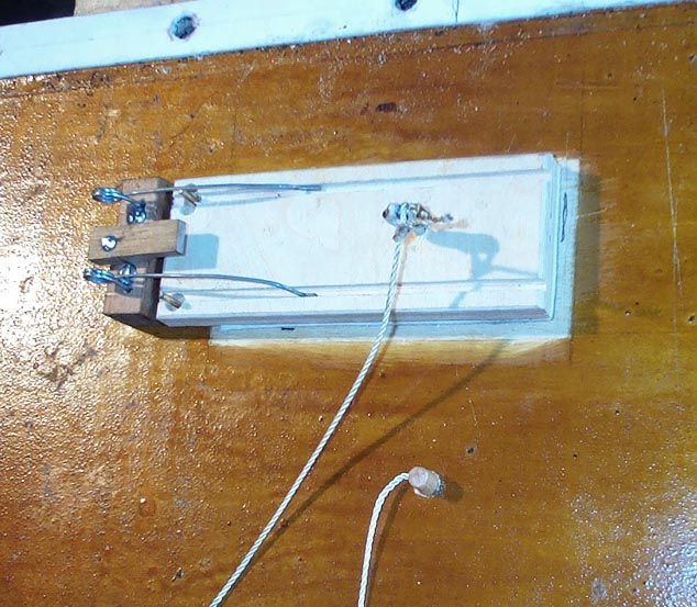
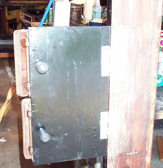
The safety pallet was installed on one of the reservoir lids. Almost everything except the end blocks, including the linkage that pulls the pallet open when the reservoir goes full, was missing, so I had to make new. I had to guess how the linkage was done, so I followed Aeolian's pipe organ practice. Strong cord is tied to an eye in the pallet, secured in the middle of the screw eye with a leather washer and shellac. The cord runs through another screw eye on the fixed board opposite the pallet, and back out through a hole in the lid. Its length is fixed by a tight tapered plug, sealed with Dow-111. The cord is left long outside, so it can be loosened if the lid is removed, and the relief setting pressure can be easily adjusted from the outside. For the time being, the cord is left long, so higher than normal test pressures can be pumped.
The following will be controversial. The organ was originally made with the base wagon firmly glued and screwed to the lower half of the organ case. Although the upper half of the case can be removed for maintenance access, the only way to get to the lower half of the insides was to lift the entire organ, supported by the end slabs, all the way out of the case, assuming the availability af a couple of husky guys. In earlier models, the innards were attached to the case with screws that require a specially made three foot long screwdriver; In may late model, the whole thing just sat inside the case, held only by two heavy iron straps connecting the keybed to the manual surround on the case. There are several disadvantages to this arrangement; the main one being that the organ outside the case is supported only by the end slabs on the lower unit, which are narrow. The removed organ is therefore unstable, and can easily be tipped over. All writers commenting on the Orchestrelle have noted this problem.
Also, the pedals were hinged to a board glued and doweled crosswise between the two pedal trim wings, a normally inseparable part of the case. This produces two problems. First of all, if the organ has to come out of the case, the pedals have to be unhinged, and left dangling on their straps. Then it is hard to pump the organ in its disassembled state. Also, the pedals are hinged to pieces cantilevered from the case; the hinge ends of the pedals are not firmly supported. One can probably not tip the organ forward by very hard pumping, but part of the pumping effort is transferred to a torsional impulse that tries to rotate the whole mass of the organ around the front wagon castors, far inward from the player's heels. This is a waste of energy. All Pianolas have the pedals hinged to brackets whose near end is free to sit firmly on the floor.
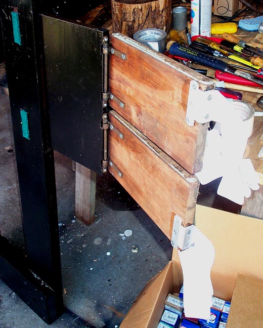
I decided to do the same thing. Since the case had to be fully knocked apart for repair and refinishing, I broke the pedal board off of the trim wings, sawed an eighth of an inch off each side, and attached it to the massive base wagon framework as shown below. Now the pedals are part of the organ mechanism and go with it when the case is removed. Also, the heel ends of the pedals are now firmly supported from the floor, as they should be. The trim wings will remain, attached to the sides of the pedal opening in the casework, but they are now only for looks.
The other part of my modification involves the lower case itself. When it is done, it will not be permanently reattached to the base wagon. I will assemble it in three sections. The front, with the manual surround and the fake manual support extension legs and manual support pillars, and the two side panels. These items are massive and plenty strong by themselves, but they will be configured so that they, not the organ, can be unhitched from the wagon and lifted off if necessary. Now the organ's works can be firmly attached to the wagon, which will support it whether the case is in place or not.
Some will shout "Impure, impure!", but I don't care. For this organ, the choice was the knacker's yard or me; I can do whatever I want, as long as I don't mess with the music itself. I will not perpetuate a design that many have noted as being flawed. Of course Kevin or Arthur (or is it Sir Arthur by now?) are in a different position. They usually work on instruments that belong to someone, and have reasonably intact cases. They have to work with what exists, and are not free to experiment.
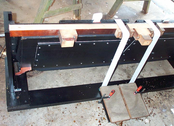
The pedal modification is done. The main crossbeam is installed. The strap rollers have simple bearings consisting of 1/4" brass rods running in holes in hardwood blocks. After cleaning out the dried up tallow and polishing the rods, a little chain saw oil mixed with graphite made them turn easily and silently. The pedal straps are attached to the pedals with glue and newly made metal strips with larger screws; the pedals are softwood, and naturally all the connections had stripped or worked loose, just like in any reed organ rebuild. The straps are attached to the feeders with their blocks and screws only, since I can not now determine the optimum pumping pedal angle.
Now it was just a matter of chasing down the leaks as before, using an ear tube and the bubble spray. A point of interest; the existing base sticks on the fixed board of the feeders (see chapter 4.7) were just nailed on, not glued. I guess they originally depended on the shellac finish to seal them, but it had long since cracked, and these joints blew lots of bubbles. Some Goopalac all around fixed that. With the flap valve openings taped, I got a time of over 11 minutes even with all the added cloth and joints in the feeders. But when the flap valves were put into service, the time went to below a minute, and the pedals felt soft. After all the trouble I went to make the flap valve seats from densely sealed hardwood, mirror smoothed with the edge of a razor blade, this was disappointing. By poking a outer, feeder flap valve open with my finger, I felt a steady stream of air. This showed that the inner flap valve set was not properly trapping the wind in the reservoir.
Examining the flap valve surfaces gave the answer. The grain of the relatively coarse cowhide was not pushed down flat on the areas where they touched on the wood. The leaky spaces between the leather fibers could be clearly seen. No matter how tightly the flap valves are stretched, this tension can not push the leather against the seats, only pressure can do that. The tension springs only make sure that the flap valve leather is right against the seats when the pressure reversal takes place, and there is no delay in closing the holes. The low pressures in the organ just couldn't push the leather hard enough so that it could "marry" with the mating wooden surface.
So I decided to try something; another impurity, I am afraid, but it worked. I put a piece of rubber pneumatic cloth, rubber side down, under the leather strip. Rubber cloth as a valve?? But Ampico did it all the time. The conditions for using it successfully seem to be; the mating surface must be very smooth and shiny, and the valve must close in the same place all the time. Unlike leather, the rubber surface can not accommodate itself with any textural or positional variations in the mating surface. The piece is just clamped under the fixed end of the leather strip, and attached to the stick at the moving end with one tack. This is completely reversible, and the cloth can be easily replaced if it does fail.
Now I knew I was on the right track, as soon as I pumped. I didn't need any clock or manometer to tell; I felt the sudden rock-hard stoppage of the pedals as soon as the reservoir filled up. The feeling that makes every rebuilder breathe a sigh of relief, when it is finally achieved. Timings of 4:11 to empty the reservoir without pumping, or one half-stroke every 1 minute and 13 seconds, to keep the reservoir full as long as I wanted.
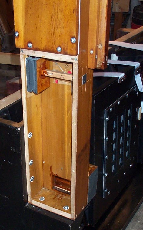
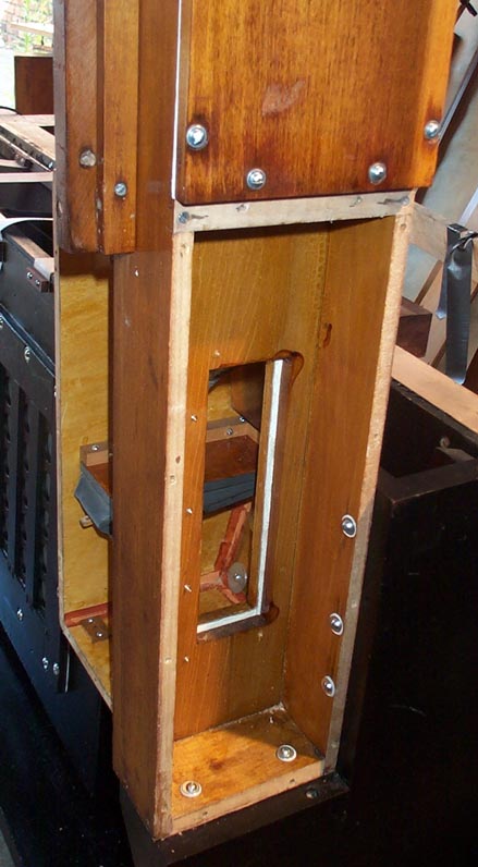
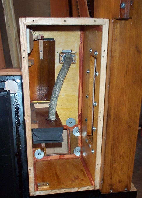
The stop action "Towers" are now attached. The left one is connected with a simple wooden elbow, just visible at the bottom. The right one is connected to the reservoir through a big box which also contains the bass windchest stop action. More about this in the next chapter. The towers themselves are firmly attached to the organ structural base. I used metal washers backed up with stretchy valve kid punchings having a small hole that sealed to the shaft of the screw, there being no gaskets to otherwise seal these screwed joints. Note that the screw holes in the rear of the big elbow-box have been enlarged, and fender washers used. This is to accommodate any dimensional changes in the wood; to allow the natural alignment of the pieces as the gaskets are drawn up. Both the big and the little elbows have gasketed joints in two planes at right angles. Modern builders avoid this configuration as being bad practice, but there are several instances of it in the Orchestrelle. One must carefully draw up these joints, alternately tightening the screws on either plane just a little, so as to compress both the gaskets evenly without misalligning the parts. These kinds of gasketed joints, which are not expected to be opened often, and are difficult to get to for later tightening, are liberally smeared with Craig Brougher's magic potion, Dow-111 sealer. This extremely thick silicone grease is clean and easy to use, is completely neutral to any traditional materials, stable and very long lasting, and forms a flexible but immobile barrier to low pressure air flow on any porous material.
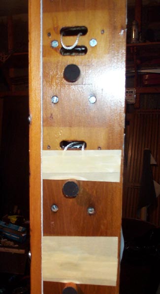
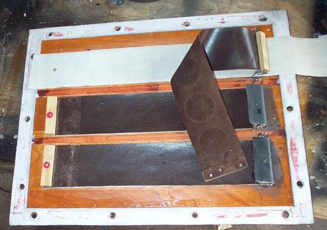
I still don't have the special materials for disc valves, so the stop primaries are not done. To continue the test, the primary holes are taped. A bit of string provides a pressure leak between the supply hole (top) and the rank pallet pulldown hole (bottom), so the pulldown remains pressurized and the pallet stays closed. A couple of the pallets needed adjustment of the springs or guide pins, and one of the pallet seats had a bit of roughness on it that had escaped my notice. Then all the pallets stayed closed, and the leak tightness was extended to these chests as well. To test the stop action, poke a hole in the tape that covers the pulldown hole; the pallet will open and spill air out of the seal where the rank is supposed to go.