 Mechanical
Music Digest™ Mechanical
Music Digest™ |
| You Are Not Logged In | Login/Get New Account |
|
Please Log In. Accounts are free!
Logged In users are granted additional features including a more current version of the Archives and a simplified process for submitting articles. |
|
|
MMD
|
|
INTENSITY OF PERCUSSION INSTRUMENT TONES BY C. N. HICKMAN
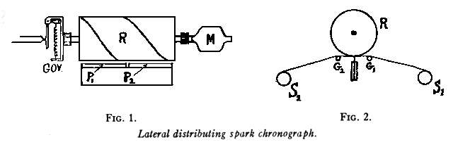
Desiring to obtain a more accurate means of recording the loudness of each note at the time an artist is making an Ampico recording, it seemed that the logical method of procedure was to measure the velocity of the hammer at the time it struck the string. In order to accurately record this velocity the use of a spark chronograph seemed desirable. If such a system were to be used it was obvious that it would be necessary to develop a special spark chronograph. The essential requirements of the system were as follows: First, the contacting member, which must be attached to the piano hammer shank, must be quite light, in order to prevent a change in the touch and tone. Second, the amount of energy in the primary spark must be quite low in order to eliminate noise and heavy currents. Third, the electrical system must be one which will be capable of rapid repetition. Fourth, it must eliminate the necessity of running the paper at high speeds which is the custom in obtaining space time records. The last requirement, at first, seemed the most difficult task but was eventually solved in a very satisfactory manner. A rotating drum, which was driven at constant speed by an electrical governing method, was provided with spiral knife edges for distributing the time interval sparks at right angles to the motion of the paper. Figure 1 is a front view diagram of the spiral drum or rotor with two spark segments immediately beneath. The paper travels between the rotor and segments. (It is obvious that by making the drum sufficiently wide and adding additional segments beneath, any reasonable number of records may be obtained.) The segment (P1) records the first contact made by the hammer and the segment (P2) records the second contact. The time elapsing between these two contacts is a function of the distance the rotor has turned in this interval. The spiral distributor, in this interval of time, has moved a certain distance to the right. This gives us a measure of the time elapsing between the first and second contacts. The spirals on the rotor may be at any desired angularity. In the instrument constructed an angle of 45° was used. The distance between two spirals is equal to the length of each segment.
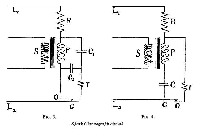
Figure 2 shows a cross sectional view of the rotor and segments with the paper passing between them. Since the space time records are distributed at right angles to the motion of the paper, it is only necessary to run the paper fast enough to get the spark records out of the way of the succeeding records. Figure 3 is a diagram of the electrical system for obtaining the secondary sparks used in the Aberdeen chronograph. Direct current of 220 volts is applied at the terminals (L1) and (L2). Condensers (C1) and (C2) are charged through the resistance (R) and inductance (P). The inductance (P) represents the primary of an induction coil. When the primary circuit is closed at the contacts (OG) the condenser (C2) is discharged. The condenser (C1) then discharges through the primary (P), inducing a secondary spark at the terminals of the coil (S). One of the terminals of coil S is the rotor spirals and is common to
all the secondary coils. The other terminal is one of the segments beneath
the rotor.
In either circuit the resistance {R) is made considerably smaller than that used in the Aberdeen chronograph in order to improve repetition. The same segment may be used again after an interval of less than one one-thousandth of a second. In order to eliminate secondary sparks a damping resistance (r) is introduced in the primary circuit of each note. This consists of a little adjustable filament rheostat. This resistance can easily be adjusted to give a single discharge between the rotor and the segment. It has already been stated that it was necessary to reduce the amount of primary energy to a point where both noise and heavy currents were eliminated. The heavy currents were objectionable because the contacts would soon be eaten away introducing inaccuracies. Heavy contacting numbers would have resulted in noise, unsatisfactory touch and tone. Several methods were tested for obtaining a record of feeble sparks. One of the methods that was suggested for recording feeble sparks, was to use photographic paper, depending on the ultra-violet ray of the spark exposing the sensitized paper. This method was fairly satisfactory but objectionable for practical and commercial reasons. Later a much more satisfactory method was developed. If the paper, which is punctured by the spark, has a coating on one side which is more or less waterproof, the spark holes may be made visible by applying a solution of dye to the coated side of the paper. Capillary attraction causes the dye to penetrate through the hole and spread slightly on the uncoated side of the paper.
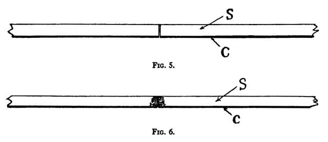
Figures 5 and 6 show the manner in which the spark holes in the paper are made visible. In Figure 5, (C) represents the coating on one side of the paper and (S) represents the porous portion of the paper. After the spark has passed through the paper there is a hole through it, which is shown in an exaggerated manner in the middle of the figure. When dye is applied to the coated side of the paper, capillary attraction causes the dye to pass through the coating and spread in the porous part of the paper. (See Figure 6.) If the paper is left in contact with the dye for a long period of time this spot becomes very large, if, on the other hand, the solution is wiped off very quickly, the result is a small colored spot on the porous side of the paper. If a heavy secondary spark is used, a solution of water with any dye, which is soluble in water, is quite satisfactory. However, if a feeble spark is used it is necessary to use a dye with alcohol as solvent. By using a mixture of alcohol and water with a dye soluble in either, a satisfactory solution is obtained for any size spark hole and any specific duration of exposure to the solution. This system permitted the use of primary voltages as low as 50 volts instead of the 220 volts necessary with the Aberdeen chronograph paper.
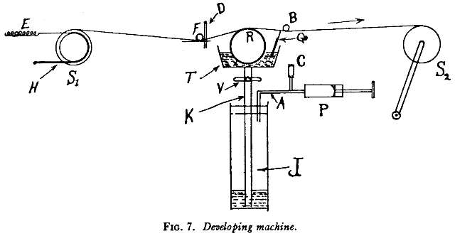
Figure 7 shows a cross sectional diagram of the developing machine. The paper passes over the roller (R) which is rotating in the developing solution (solution of water, alcohol and dye). The paper then passes over the rubber squeegee (Q) which scrapes off all the surplus developing solution. Since a paper with waterproof coating is used, it is not necessary to dry the paper after leaving the squeegee but it may be immediately wound up on the spool (S2). The spool (S2) is provided with a crank which is operated by hand. There is a friction brake on the spool (S1) from which the paper is to be pulled. This regulates the amount of tension on the paper and keeps it constant. The idler rod (F) is floated on the paper and helps smooth out irregularities in the brake tension. For convenience in inserting the developing solution into the tray (T) the solution is placed in the bottle (J). A tube (K) having a valve (V) extends from the bottom of the bottle into the tray (T). There is a pump (P) by which air may be pumped into the bottle through the tube (A). This forces the developer up into the tray (T). The valve (V) is then closed. When the liquid is to be removed from the tray, the valve (F) and the port (C) are opened, permitting the air to escape and the developer to run back into the bottle (J). A great deal of data was obtained m the Laboratory to determine the accuracy of reproducing hammer velocity with a constant pressure in the wind chest of an Ampico. It was found that the hammer velocity could be reproduced with an accuracy of better than five parts in one thousand in playing a single note. Considerable data was obtained in order to find the effect of measuring the velocity by changing the distance between the contact points. It is interesting to note that as long as the first contact was not made prior to the time when the hammer was about 12 mm. from the string, that the velocity measurements remained the same, regardless of the distance between the contacts. In other words, if the first contact is made 11I mm. before the hammer strikes the string and the second contact is made 1 mm. before the hammer strikes the string, the velocity is found to be the same as when the first contact is placed 6 mm. before the hammer strikes the string and the second contact 6 mm. before the hammer strikes the string. All this was done in order to show that the velocity of the hammer does not change materially during the latter portion of its travel. In other words, after the hammer reaches a point about 12 mm. from the string the velocity remains practically constant until it strikes the string.
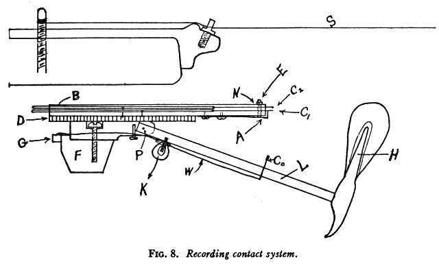
Figure 8 shows the manner in which the contacts are made by the motion of the hammer. The contactor (C0), which is a light silver bar, is attached rigidly to the shank (L). This contactor is connected to the bus bar (G) by means of a small flexible copper wire. There are two silver wires, C1 and C2, which make contact with the contactor (C0). As the contactor (C0) touches the silver wire (C1), the primary circuit is closed and a secondary spark occurs between the rotor and the segment to which C1 is connected. In like manner, when C0 contacts with C2 another spark occurs between the rotor and the segment which is connected to C2. The bars {D) are the distributors to which the contacts (C1) and (C2) are connected. The contact (C2) has a definite down stop located so that the contactor (C0) engages it about 1 mm. before the hammer strikes the string (S). The contact (C1) is adjustable. Its down stop being the spring (A) which is controlled by the screw (E) and locknut (N). This contact is made about 4 mm. before the hammer strikes the string. The distance between C2 and C1 is adjusted by means of a micrometer. It is interesting to note that after eighteen months daily use in the Recording Department, the contact distances for all the hammers were measured and with the exception of three notes were found to be correct to better than 1%.
Curve #l shows the velocity of a bass and treble hammer respectively for various Ampico wind chest pressures. The dots on each curve represent the Ampico steps of intensity. The velocity of the hammer and also the wind chest pressure for each of these intensities may be read from the graph. The velocity of the treble hammer is appreciably higher than the velocity of the bass hammer, however, the mass of the bass hammer is greater, so that the energy remains approximately the same. It is the intention of piano builders to keep the loudness of the bass and treble portion of the piano well balanced.
Curve #2 shows the steps of intensity of the Ampico plotted against the logarithm of the square of the hammer velocity. Here it is seen that the slopes of the curves for the two hammers are almost identical. The increase in energy can be determined directly from the logarithms and shows that in each hammer there is an increase in loudness corresponding to 18.2 decibells.
Curve #3 shows Ampico steps of intensity plotted against sensation units or decibells. The only assumption that is made here is that the sensation level for the lowest Ampico step for a single note is 30 decibells (Sensation units). The loudest Ampico step brings the intensity level up to 48.2 decibells. This curve represents the values for both bass and treble hammers. This is on the assumption that the intensity level in each hammer starts at 30 decibells. This is an arbi trary value but the value is the same for both hammers because the Ampico, before leaving the factory, is adjusted so that, for the lowest intensity, equal degrees of loudness are obtained from all notes. The value of 30 decibells is arbitrary, being chosen according to the best judgment available. While this intensity range of 18 decibells may seem small, it should be remembered that this range is for a single note. When an artist is playing fortissimo and using the sustaining pedal, it is possible to build up an intensity perhaps twenty times as great, which would add an intensity of about 13 more decibells to the range of the piano, giving a total of about 31 decibells. It has been shown that the velocity of a bass hammer is less than the velocity of a treble hammer for the same level of loudness. This change in hammer velocity is not an abrupt one but takes place gradually from one end of the piano to the other. This is to be expected since the hammers are all different in size. They are moulded in a tapering form and then later sawed apart. In order to avoid the necessity of using a different measuring scale for each hammer, the contact distances in the bass portion of the re cording piano are made smaller than those in the treble. Each hammer has a different contact distance. The total variation from note #l to note #88 is about .030 of an inch. This gives approximately .0003" difference in contact distance for adjacent notes. It is hoped that chronographs of this type may be useful for other purposes. A great number of records may be made simultaneously on stationary paper. The paper may, however, be moved along slowly. It is only necessary to move the paper about 1/32", after one record has been made in order to obtain another record from the same segment. It is also hoped that the recording paper principle which has been described may be useful to others.
Images, TIFF-Huffman encoding: jasa0.tif 63 Kb
06 April 2002 |
|
|
|
|
|
|
|
|
|
CONTACT FORM: Click HERE to write to the editor, or to post a message about Mechanical Musical Instruments to the MMD Unless otherwise noted, all opinions are those of the individual authors and may not represent those of the editors. Compilation copyright 1995-2026 by Jody Kravitz. Please read our Republication Policy before copying information from or creating links to this web site. Click HERE to contact the webmaster regarding problems with the website. |
|
|
||||||
|