[ Part 1 of this two-part article appeared in 200114 MMDigest; see
{ https://www.mmdigest.com/Archives/Digests/202001/2020.01.14.01.html
This project -- to bring into reality a new improvement upon an early
original design -- continues. To begin, first a few prefatory remarks:
Not generally known is the fact that later period Welte-Mignon
(Licensee) encoding included usage of sub-intensity levels as did
the Ampico "B", but without need of a dedicated tracker bar duct (0T)
nor of any additional mechanism to achieve it.
The neat trick was accomplished simply by means of the opening and
closing of the "Sfz. P." in the bass/treble (ducts 5/94 respectively),
during or before a note or notes were to be played, this then bleeding
some gauged quantity of atmosphere into the regulators and valves
within the bass or treble halves, and thereby lowering their vacuum
levels from normal.
My having been not all that sharp as to uptake generally when younger
(and now as only slightly improved), such seemingly random use of
these 5/94 ducts as I'd observed did puzzle me. It was to be that ace
Welte-Mignon encoder, collector, restorer and friend with us no longer,
Kenneth K. Caswell, who later would explain to myself about their
operation as well as much more.
Eventually, as it was to be, this newly-effected design would prove --
in combination with note compensation as well, just as for pedal --
to produce remarkably even pianissimo play regardless of the frequency
of pedaling action ongoing, this for the very best and true Welte
Mignon re-enactments but, not for any as closely repeated notes, such
difficulty being of separately identifiable trouble for special
addressing later, elsewhere.
(Though for any having interest, as simply stated, it is relating
to mis-distributions of energy resulting in effects offensive to
discriminating musical sense, specifically telling distortions of both
the temporal and dynamical fabrics of musical play. Only too vexingly,
its real-world fix is not nearly so simple, as is that for our present
object.)
In closing these remarks, for some wise inclusion of a bit of
authoritative historical context, I here quote from the last paragraph
of the section titled "Pedal Compensation," found at page 29 of the
splendid Ampico Service Manual of 1929 -- "The above compensation is
one of a number found in the New Ampico which helps to produce an
outstanding evenness and smoothness of playing."
Indeed it did, when all things were rendered finally as ideal. And so
too does our equivalent newer design, as applied to the Welte-Mignon
(Licensee) and by extension potentially, to the Welte-Mignon generally.
(Creative, willing minds doubtless-so will be able to transfer my
design easily, for use with all other types of Welte-Mignon actions.)
Within the attached drawing for my Damper Compensator Pneumatic [Ref. 1]
will be found several of numbered figures. In-turn, I'll address each
with commentary, beginning with the first:
1. Just as titled, this shows the front of the Expression Pneumatic
with Compensator attached. Above it is the legend "to be positioned
..." which underscores the need for precise alignment laterally of the
device, so as to achieve an exact like-positioning to the originals
connecting tab.
This is a most important detail. There are two tracker-bar-sized
elbows chosen and placed so as to produce the least interference to the
action of both the Expression Pneumatic and Compensator. Shown also
are its fine-adjusting screw along with a small punching of thick pump
cloth, this to seal-off the screw attachment hole, after final
positioning and tightening.
(With an expression pneumatic assembled to the whole mechanism, do this
first with a bit of double-sided Scotch Tape affixed to a Compensators
back. After aligning, this so that the length of the hook-eye connector
is exactly parallel with respect to the threaded connecting wire it
pulls and its travel, press it firmly-on, then spot for the correct size
of pilot-hole. After drilling and securing by the specified wood-screw,
remove all, detach the tape and reassemble. If done carefully the
result with be found perfect, and it achieved with the least amount of
trouble.)
2. A side view is here, showing the vertical positioning of the
Compensator with its simple return spring. These feature no coil to
them, it being unnecessary as the tiny bellows' motion is quite minute
even at its front as observed, and therefor really requiring of no
countering force constancy. Two of small gauge (say, of wire size
#55 to #60) on each side will do nicely. It will be noted that this
pneumatic is operated by a higher regulated vacuum of around 15 inches
water-gauge as supplied to the sustain pedal. (In the Licensee W-M,
this being regulated down from static pump level.)
The object of the game is to have just a minimum of combined
opening spring tension, this set so as to result in no perceptible
dislocation whatever of the connecting hook at its pianissimo setting,
simultaneously as a note or notes or chord are played. (For here
is where the frictional forces will be found their greatest, as the
interior of the regulator will have its highest suction differential,
of say around 4 water-gauge inches verses a behind-the-knife-valve
high static of around nine or ten times that?)
Its covering should be of ordinary thin key-striker cloth, though Schulz
type (still thinner) would be even better. It is to begin its closing
motion from fully-open.
3. This is showing the same as Fig. 2, here mostly for completeness'
sake.
4. Here can be found the complete dimensioning for the top of the Shift
Pneumatic, all being self-explanatory.
5. Just as with Fig. 4 are seen here too the positioning for the
attachment screw and strike-pad of thicker action cloth of, say, 1/8".
(Though the force resulting here might be high upon contact, the total
mass involved and its motional distance and final velocity are but
little, and therefor possessing of but minute energy for any needed
dissipating, and so the result thus awarded is effectively silent
operation. It is interesting to watch so.)
6. This is a side view of the entire as assembled. The hinge appearing
at above is of a thinner pump rubber cloth, the two boards here being
of no-more-than 1/10" separated, or slightly less, even. The edges, of
course, being not folded-over but requiring only a minute application
of plastic glue at their seams, for achieving of a good seal.
The #4-40 machine screw insertion begins with the specified drilled
hole first charged lightly with super-glue inside it and then, when
dried, tapped as if metal (for ease of alignment and sureness of cut,
hold the tap in a drill-press chuck with v-belts and return spring only
lightly-engaged, turning by hand slowly 'till through).
This once-done, then glue-charge again post the firsts hardening,
with the tap being run-through the threads a second time manually.
It will self-align if carefully started-straight. This will result in
a permanent, sealed-tight threaded hole that will never give-way even
in soft woods. For delightfully smooth adjustment ease, lubricate
_only_ with lamb fat.*
With enough expended patience, a permanent and easy operating air-tight
firm grip on the threads will be attained. Also, it might be noted that
the screw-head specified is a six-sided (hexagonal) one. This will be
found far easier of use, during any needed side-wise adjustments, than
would an ordinary slotted type.
* Traditionally, so it seems, once a year during Winter, some organ
builders hold a 'rendering day' for lamb-fat. It is a sort-of Germanic
celebration I think, surely marking of something-or-other, but of just
what I never knew. All were to bring their saved frozen trimmings
gathered over the previous year for heating, collecting, straining and
canning, the result being for use in the coming year.
As a general lubricant, for work with wood and leather or for screw
insertion, its qualities are unrivaled. It costs nothing and, will
last almost forever. Also it will not decay, nor do undesirable
organ-chamber creatures like to consume it.
7. This dual-view makes clear the thickness of the boards and their
borings, and is self-explanatory.
8. Here is shown the form and dimensions of the Connecting Arm for
the original hook. Again, all here being self-explanatory.
9. And the bottom view of the above: The 0.177" hole is to be bushed
with ordinary flange bushing cloth, this leaving afterward a hole large
enough so as to accommodate for insertion of the original connecting
hook complete with some tensile-grip to it; any relieving of it here
being unnecessary.
End of remarks.
For the fun of it I created our drawing so as to nominally appear as
it might have, had it been generated back-in-the-day in the very early
Thirties, but only found now in our present, it having never been
utilized because at 'the end' of a most marvelous Licensee run.
I suggest printing it same-size (7.966" x 10.51" exactly!) as centered
on thicker 8.5" x 11" laid paper, say that is toned-buff or cream.
Its resolution is high, being at 600 dpi., so it should print-out and
present nicely for any saving/archiving.
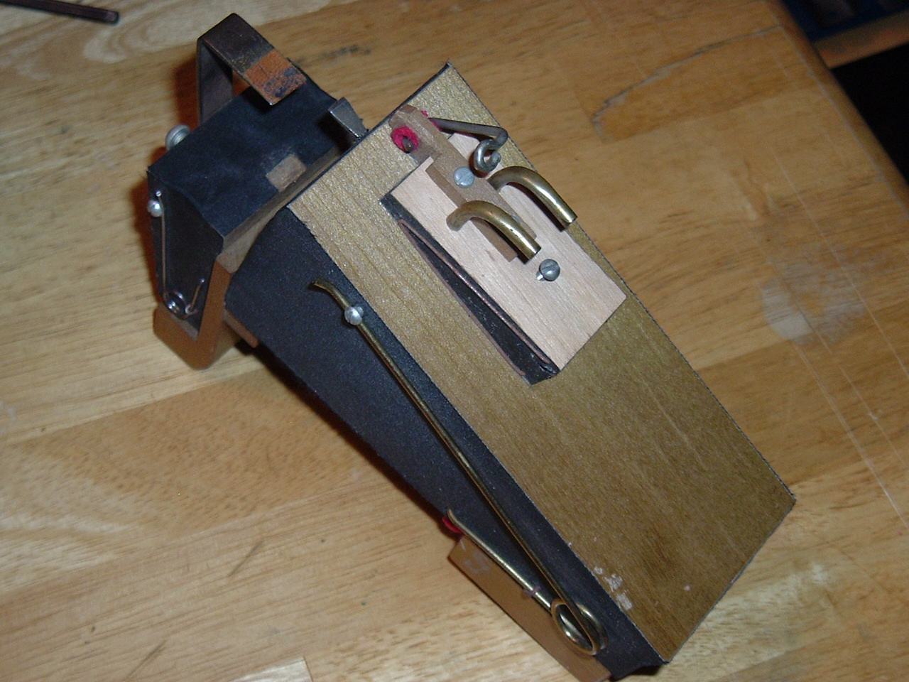
At Ref. [2] I have included a close-up photograph of an actual mounted
Compensator. This is one of the pair that were part of the mightily
struggled-over device of ca. 1967, included before as an image of this
writer with Part 1. [Ref. 3]
I am here for questions such that any building reader/contributor might
have. For these I suggest that they might be ones better as-published
than not, so that all could benefit from any answers provided but,
otherwise P-Ms are invited too, and will be received and answered with
pleasure.
Jim Miller
Las Vegas, Nevada
References:
1. Welte-Mignon (Licensee) Pedal Compensator Drawing
https://www.mmdigest.com/Attachments/20/09/28/200928_063024_PianissimoCompPrintHi-Res.png
2. Pedal Compensator Mounted to Welte-Mignon (Licensee) Expression Pneumatic
https://www.mmdigest.com/Attachments/20/09/28/200928_063024_PedCmstrMtd.JPG
3. J.M. Nearing the Deadline
https://www.mmdigest.com/Attachments/20/01/15/200115_153800_J_M_deadline.JPG
|
 Mechanical
Music Digest™ Archives
Mechanical
Music Digest™ Archives