Chapter 9.1 The Roll Motor, Introduction and Preparation
Kevin McElhone has describes several forms of the roll motor used during various Orchestrelle construction periods. Mine came with a roll motor of a peculiar type, using "French Feeder" (three board; moving center leaf) which I have only seen on one other occasion; on an early compact format Themodist player piano where there had to be room for the tempo regulator above the deck, and the motor had to be unusually short. Since the player parts had been removed from the organ in the past, I can not be sure that this replacement motor was the original, or even contemporary with the style used when my instrument was built. In the case of an Orchestrelle, the low pressures (2.25 " WC) require the use of very large pneumatics, so the double pneumatics were chosen to allow three big sets to go in the same space taken by Aeolian's usual arrangement of center hinged "rocking" double pneumatics.
Being a pressure organ, the motor is enclosed in a pressurized box, with the center port (where vacuum is normally connected) gasketed to openings to atmosphere on the sides of the box. With the air supplying the "vacuum", it works just like a player piano motor, with the pneumatic forces tending to close the bellows. Like any Aeolian motor, there are three sets of bellows, giving a total of six pneumatics acting successively on the crankshaft.
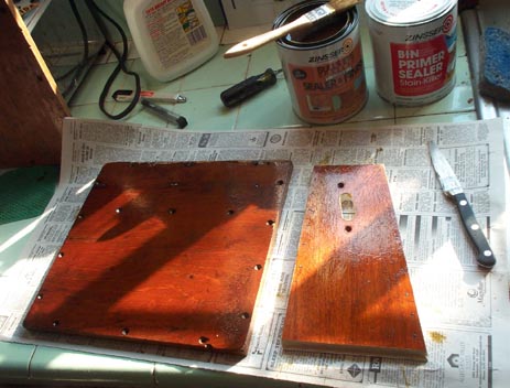
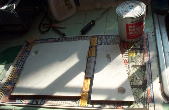
The six boards making up the box are made of 1/2" mahogany veneered poplar core furniture plywood. They had become water stained and delaminated in places. The veneer was glued back as well as possible, and the outside surfaces were given new coats of shellac. To seal any potential leaks through the porous mahogany to any poorly glued interface in the plywood, the entire interior was sealed with Zinsser B-I-N, (see Chapter 8.1), including all the holes where end grain showed.
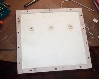
New packing was glued to all the edge joints, and gasket punchings were glued around the three holes where screws from the outside attach the flimsy back pneumatic leaf to the rear wall of the box.
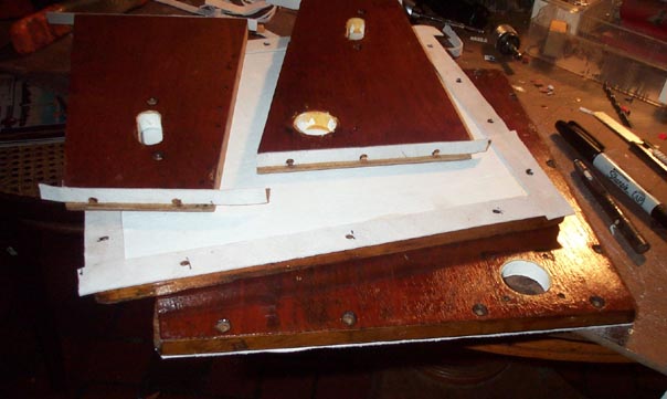
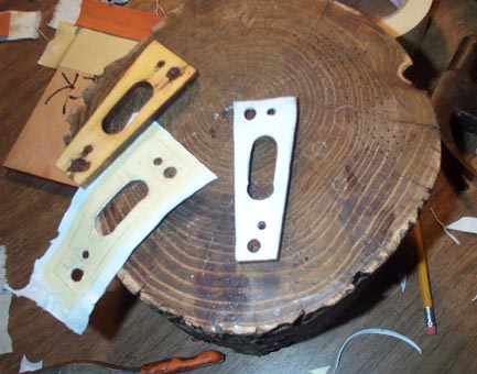
Two wood spacers that go between the ends of the motor and the box sides were gasketed. Rubbings using masking tape and a soft pencil were made as an aid to punching the leather.
The place where the shaft comes out of the box is a problem. It would be impossible to locate a bushed hole in the box that would be in exactly the right place to seal around the shaft without binding. On this motor as received, the shaft hole in the box was large, and a little square of wood with a bushed hole was screwed on around the shaft after the whole thing was assembled. But dimensional changes in wood and compression or replacement of the box gaskets cause the bushed hole to end up in the wrong place over time. Several sets of different screw holes for the bushing block around the box hole were evidence of futile attempts to relocate the bushed hole properly around the shaft in the past. So I decided to discard the plain bushing block, and replace it with a floating bushing, like Aeolian used in their 116-note pipe organ roll motor boxes.
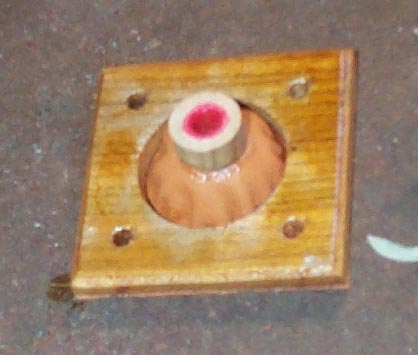
The very deeply drawn pouch's center can move laterally about 1/4" in any direction, to allow for any misalignment of the shaft and its box opening. Lay a big piece of pouch leather face down over a 3/4" high pile of coins, then push the glued wooden square down over this, to set the pouch. Smooth the wrinkles in the glued edge and trim; this lap of leather also serves as the gasket for the whole thing. The busing in the wooden center is very loose, so the shaft turns freely. The actual seal that keeps the wind in the box from escaping is a cloth punching. When the box is under pressure, the pouch inflates enough to press this punching against the hub of the sprocket, where the actual seal takes place.