Chapter 16 - The Roll Drive and Transmission
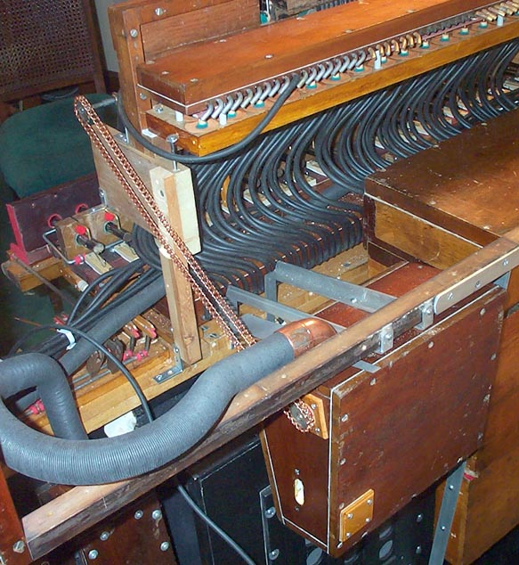
Since my instrument had been converted to a finger organ, there was no spoolbox installed, and the spoolbox that I got must have not been the original one. This spoolbox had most of the metal parts of the transmission, but they were badly corroded. So the first step was to take everything apart, and clean them up with Naval Jelly and steel wool. Then they were installed on the ends of the spoolbox. Because the spoolbox is pressurized during roll play, the inner surfaces of the transmission frames are gasketed to the box with pouch leather.
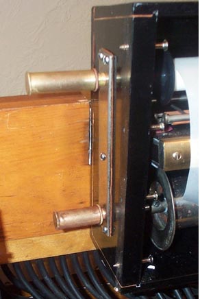
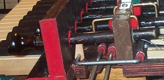
The transmission is the shifting high speed shaft type. When shifted to the right, a collar with a pin engages a pin on the hub of the large reroll sprocket. This sprocket is prevented from shifting with the shaft by a slot in its hub which engages the outside of the lower frame. When shifted to the left, a pinion on the end of the shaft engages the large playing gear on the the end of the take-up spool. This shaft is supported by a separate small frame at the bottom, which has a slotted screw hole at the front end. This enables one to swing the little frame up or down to adjust the depth of engagement between the pinion and the gear. This adjustment is important; the gears make a lot of noise unless the engagement is exactly correct. The far end of the shaft is supported by a bracket near the motor sprocket, which is also adjustable. The larger frame contains the bearings for the two right chucks.
Because of the way the roll spools were made, the right edge of the paper is always held exactly 9/16" from the face of the roll chuck, 6-to-the-inch roll instruments typically have no tracking device. The bearings for the roll drive chuck shaft and a similar chuck shaft for the removable take-up spool, have knurled brass screws and jam nuts for permanently adjusting the lateral position of the paper.
If a properly tapped down 6/in. roll mistracks, it is usually because the right flange has come unglued from the core, and allows the paper to shift rightward. This happens easily, and all sorts of measures; nails, special pins, or eyelets swaged onto the tenon, were tried by various roll makers to prevent this.
The spring loaded chucks on the left side are elaborate arrangements of brass tunings, which I have never seen before.
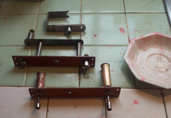
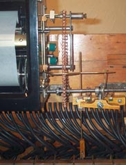
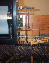
Unlike on earlier models, there is no "Reroll" drawstop or other control handle, and all the control linkages were missing. This mystified me; how did one switch to reroll? Kevin McElhone kindly set me straight. On later models, the rightmost drawstop, marked "Manual to Pneumatic", which turns on the keyboard, also switches the transmission to reroll, and also turns off the wind to the spoolbox. There were various screw holes on the stop board in that area, and a toggle slot in the stop shaft, but no actual parts. So I had to guess, and added another roller, and a toggle link for that stop.
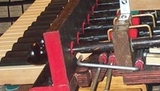
The other end of the new roller, not shown, raises or lowers a new threaded rod. I had to devise a new rocker that translated the vertical movement of this rod to lateral motion of a follower that shifted the transmission shaft. Probably nothing like the original design, but it works. I also made a new lightly spring loaded playing brake, that is pulled back during reroll by a post on the rocker.
The spoolbox had a wind cutoff box on the rear of
the left hand extended part of the box where the opened window is stowed.
This box contained two slide valves in series, According to Kevin,
this was used in earlier configurations, where either the "Reroll" drawstop
and the "Manual to Pneumatic" drawstop would cut off the wind. Not
wishing to add any more linkage and associated friction to the stop action,
I replaced this valve box with a new pneumatic cutoff. When the "Manual
to Pneumatic" stop is pulled, the keyboard pallet touchbox is pressurized,
closing the valve.
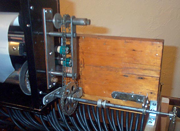
All that remained was to install the motor and the chains. I knew that it went somewhere n the back, but I had to guess how to install it. This is the way it fitted best. The gray wedge shaped fiber piece under the hose flange is the temporary temp valve, until I get around to making a new one to replace the original that is missing.