Chapter 25 - Final Installation of the Spoolbox
You can skip this chapter, if your spoolbox fits properly as found.
During preliminary assembly and checkout, the spoolbox assembly was temporarily rigged up on scrap wood supports. Until the swell box and shutter system was rebuilt and installed, I had no way of knowing exactly where its final position was. However, the bottom edge of the swell shutter frame clearly showed the pattern of grooves which were cut to clear the hooks used to attach the front frame of the spoolbox, thereby determining its exact vertical and front-to-back location. Also, the gaps cut into the bottom boards of the swell box approximately matched the outline of the rear of the spoolbox.
But the spoolbox that I got from the prior owner is not original to my particular organ. Although its overall shape of the box itself closely matches the space in my organ, it would not fit as originally configured. This spoolbox, apparently for an earlier instrument with a deeper or taller swell box, was originally meant to be rigidly attached to the primary valve assembly. Not knowing any better, I had rebuilt the spoolbox and primary in that configuration. In my organ, the valve assembly on the back of the spoolbox interfered with the bottom panels of the swell box. Reshaping the openings in the swell box would not help; the back of the primary assembly and its wind hose would still interfere with the Helmholz resonator array on the lowest rank inside the swell box.
So it was necessary to reconfigure the whole thing, ending up with the spoolbox by itself, and the primary valve assembly as a separate component located lower down in the space below the swell box.
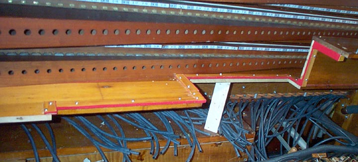
This shot shows the bottom pieces of the swell box, as originally configured. The light places on the edge f the wood shows where the existing opening had to be trimmed to accommodate my spoolbox.
I had no way of knowing how the spoolbox was supposed to be supported in the case. So I decided to hang it from a piece of strong 1" angle iron, laid along the bottom of the space just behind where the bottom of the swell shutter panel goes. Also, the bottom swell box boards, and the bottom rail of the swell panel itself, had sagged a little over time. The angle iron cured this as well. Two thumbscrews (not visible behind the front of the angle) screw into the top of the spoolbox at either edge. Thus the box hangs from the angle iron, and can thereby be adjusted to the correct level.
The wooden panel across the back of the original spoolbox, that held the primary in place, was discarded. A narrower, new board across the bottom of the spoolbox rear, was made to hold the extended parts of the transmission. A bit of this can be seen at the lower right of the box.
Two pieces of aluminum bar (impossible to photograph deep inside) were fitted, extending forward from the manifold panels. Holes in the ends of these bars snap over pins screwed in the ends of the spoolbox framework, to hold the box in the correct vertical orientation, and keep it from swinging on its suspending screws.
To minimize sound leaks from the swell box, all the edges where the spool box went through the swell envelope were trimmed with red felt. It was impossible to cut the openings in the bottom board to exactly match the spool box outline, so these were cut oversize where necessary. Then strips of wood, with felt on the bottom and one edge, were made. They were cut to length, and stuck down around the openings with rubber cement, by reaching in behind the mounted box. Then the box was removed, and the strips were screwed down, resulting in a tight sound seal all around the back of the box.
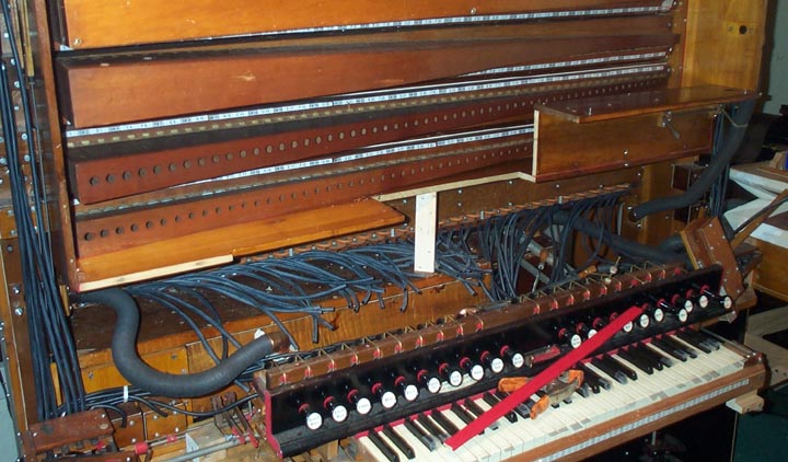
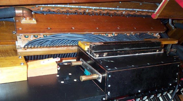
Now, the spool box could be swung face down, and the tubing connections completed. One can see here the new placement of the primary valve assembly, lying on top of the bass chest. Since the tubes leading down to the keyboard valve chest ended up short and perfectly vertical, I suspect this is where the original primary chest was located in the first place.
First the short tubes between the key valve chest and the primary were installed. This held the primary box firmly in place. Then the tubes from the primary and the secondary pouch rail were fitted. Finally the tubes from the back of the tracker bar were fitted to the primary tube rail. One can see here, how the spool box can be swung down, to gain access to primary and secondary valves. It's tight, but nobody has ever accused Aeolian of designing anything that was easy to get into.
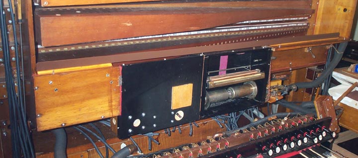
Also, this shot shows the spoolbox wind cutoff valve on the back of the extension board where the spoolbox glass window is stowed when open. The plugged holes in the center of this board shows where the valve was originally located. The valve had to be moved down and to the left, to clear the bottom swell box panel. Note the pneumatic and valve disk to the right of the cutoff valve. This is an item I had to add, since the last time I discussed the spoolbox. I discovered that when the instrument was switched to 'reroll' and the wind cutoff valve closed, wind trapped in the spoolbox caused to notes to continue to play annoyingly during rewind. The pneumatic is held closed by a spring. When the key pallet chest is winded by the "Pneumatic to Manual" (reroll) stop, that pressure inflates the pneumatic (as well as the cutoff valve pouch); opening the valve and venting the spoolbox immediately.
At this time, I took the opportunity of changing out these tubes, as well as all the other tubes, with the new Schaff 7/32" tubing. When I first assembled the organ for testing, I used 7/32" tubing from Player Piano Company. This product was the only kind available at that time, but it was not very good. Presumably it was Neoprene, but it had so much plasticizer that it looked and felt greasy, and often popped off the nipples of its own accord. Last year, Craig Brougher persuaded Schaff to add 7/32" ID to their line. I bought some, and it fully met the high standards of other Schaff tubing. Just enough undersize so that it goes on the nipples easily, but won't pull off without a good, firm tug. Craig is to be congratulated for getting this essential product back on the market.