Chapter 24.2 Assembling the Swell Shutter
The side and top panels, and parts of the bottom panels of the swell box, are assembled onto the organ. To avoid uncontrolled excape of sound, and to avoid sympathetic rattling, all the places where these part join up, were edged with medium nameboard felt strip. This seems not to have been done originally, but what the hell; let me have my fun!
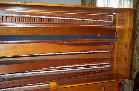
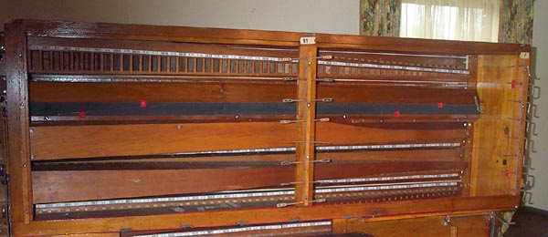
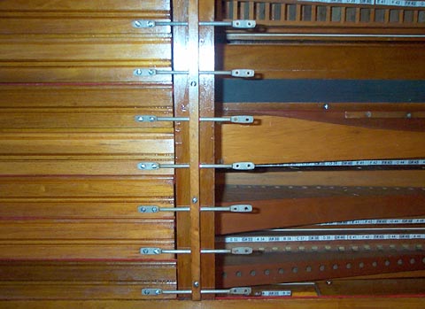
The swell shutter frame was hung up in its place. To make removal easy, this frame is mounted by dropping it down on locator pins driven into the floor of the box, matching holes drilled in the bottom rail of the frame. The top rail of the frame is slotted in three places, fitting over L-hooks driven into the top panel. These L-screws are turned 90 degrees, to firmly lock the frame in place. The shutter hinge rods for the right and center rotation points are clipped under the bushed flange strips now, since thier flattened ends are too big to be slipped into the bushed holes. The left end rods have one plain end, and can be inserted into the bushed holes, so they are just screwed to the slats, for insertion later.
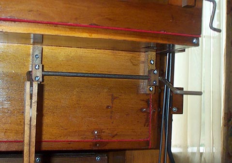
There is a roller crank under the floor of the swell box, to transfer the movement of the knee-swell linkage to the outer side of the swell box. Chapter 11 shows more detail of the lower parts of the knee-swell linkage. The split block flanges were rebushed, as in Chapter 11, and remounted. These blocks had to be carefully shimmed with paper, to get them parallel and plumb to the board, and allow the crank to turn with perfect freedom.
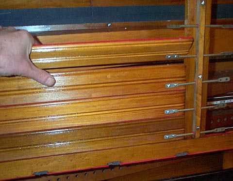
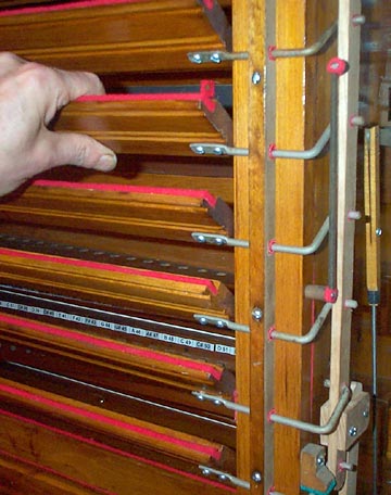
The slats in the left hand aray were installed and screwed to the center rail hinge rods. Then the right hand slats (not shown) were screwed to the other ends of the center rods, and the right hand crank shaped hinge rods. Some of the screw holes were worn and loose, so it was necessary to reinforce the the holes with bamboo skewer pieces glued in. And some of the screwholes had to be "shifted" with such pegs, to even up the spaces between the slats, and to make sure the hinge rods were perfectly horizontal.
The parallel bar and the linking piece, and the return spring, were installed.
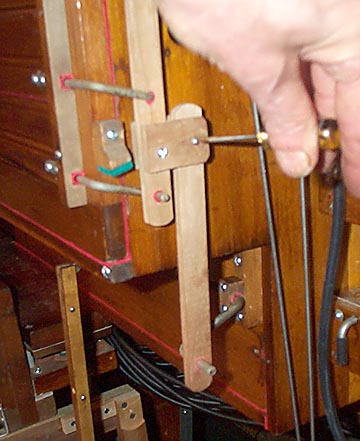
After a while, it seemed dumb to me, to always have to unscrew the link piece, every time the swell panel was taken down. So I modified the link piece, by replacing the lower hole, with a bushed slot.
Now the link just drops over the crank, but the system still works reliably. The crank arm is long enough so that he link won't slip off. No more problems; the swell panel lifts off and on easily, with no more fussing with the linkage.