Chapter 26.1 - Making the New Tempo Slide Valve
You can also skip this chapter, if your instrument came with its original tempo valve.
The tempo valve was one of the items that did not come with my instrument. I had a similar Aeolian tempo valve from a pipe organ, which gave me some design ideas, but it could not be reused. Because of weakness of the unrebuilt organ motor, someone in the past had carved a big groove on the bottom of the slider, in an attempt to increase the capacity, rendering it unusable.
I decided to make a brand new valve, rather than trying to fix the old one. While I was about it, I devised a different configuration that would be easier to adjust and calibrate.
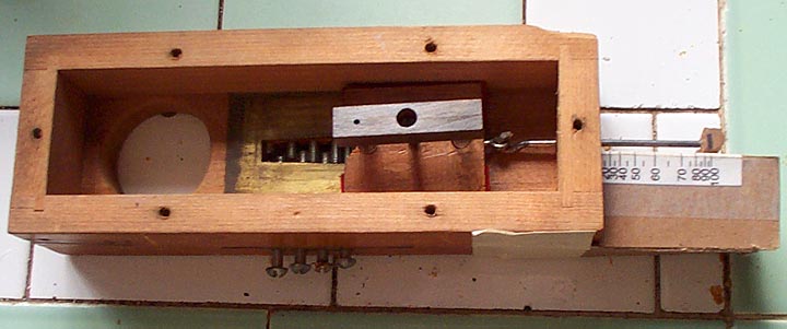
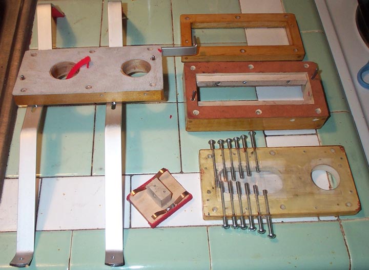
The valve consists of four layers, forming a block.
From the bottom up:
1. The bottom, fixed base layer holds the glued-in hoses.
The mounting bars attach to this layer; once the system is installed, it
stays in place, forming a foundation for the whole thing.
2. The valve slot layer includes the plastic sheet with the shaped
tempo slot. If the assembly screws are removed, the layers can be
pulled apart, and this board can be pulled out for working on the calibration
of the slot.
3. The body layer contains all the moving parts. If the
stack is separated to work on the slot, the linkage can remain attached
to the works, so no reassemble or readjustment is needed when the box is
reclosed.
4. The lid layer was made as a 'frame', with a plastic window
for viewing the insides. On could say this was hot-dog perhaps, but
it is not unprecedented. Aeolian used windowed chests for various
organ logic components, such as organ contact boards.
The four layers have snugly fitted aligning pins, so the parts go back
together without spoiling the adjustment of the valve.
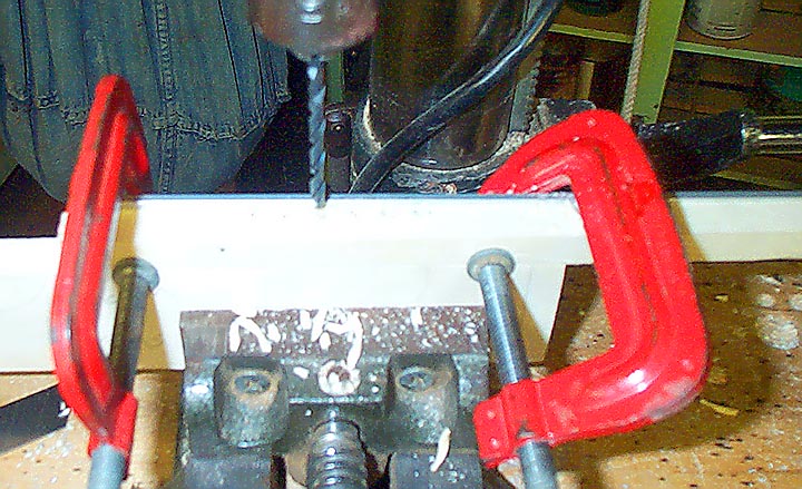
One of the unique features of Aeolian organ tempo valves is an array of interlocking #10 machine screws just below the tempo slot. These are used to accurately calibrate the tempo at each setting. Getting the rows of the screws to interlock at the center is a bit tricky. The valve layer was divided into two halves; each half drilled separately. First a template was drilled, using a bit of screw and a thin shim between each hole so that the holes were spaced properly. A strip of aluminum clamped behind the wood made sure that the holes were close to one edge as possible.
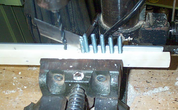
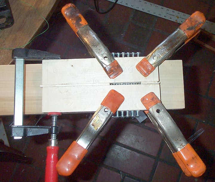
Then the template was used to drill both halves of the board. The screws were put in part way, and nested together at the center joint. This made sure that the screws from both sides interlocked properly.
A rough layout of the slot was made; the plastic sheet was glued on, and the slot was roughed out with a drill. Then the final outline of the slot was made with a file.
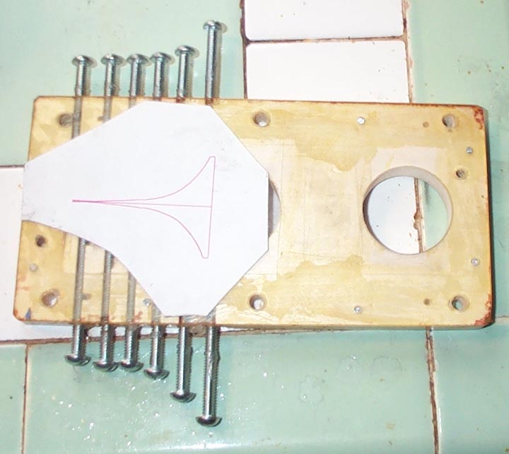
I have to admit that the pattern I originally conceived, based on a player piano tempo slot, did not work. I had to try again with another piece of plastic to get it right. The problem is that organ rolls often use very slow tempos; as low as 35, and rarely higher than 80. Unlike in a piano, the tempo has to be accurate at these low values, as well as across the entire range. The plate ended up thus, finally cut, polished, and graphited:
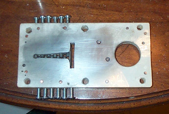
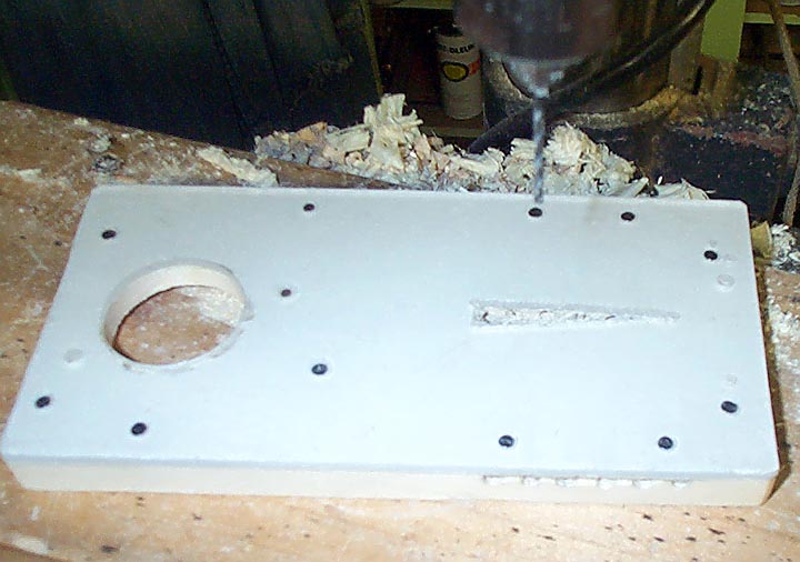
This picture shows another feature unique to Aeolian organ tempo valves. There is no bypass valve connected to the reroll linkage. When one rewinds a roll, the tempo lever has to be moved all the way to the left, above 95. To get reasonable reroll speed, the high end of the slot is enlarged considerably. During calibration, I found that the effects of this big opening 'fed back' to lower tempo values, making them too fast. So a bit of celluloid had to be glued in to separate the big opening from the rest of the slot. (The old valve plate had a thin brass crossbar at this point; I did not realize that this was essential when I first made the plate!)