Ampico B Spool Motor
Schematic Diagram - Ampico B Note Sheet Motor and Governor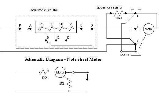
For 110 vac 60 Hz mains the motor nameplate will say that it's a 110-volt
ac/dc (universal) motor. Adjustable resistor R2 is set to
25 ohms and the governor resistor R1 is 360 ohms. If the piano
must be used with a different mains frequency or voltage (up to 125 vac),
first adjust the tapped resistor for the highest resistance which will
still provide enough motor power under the greatest load. This is
during rewind when the re-roll brake is briefly applied. Second,
starting with a low value, increase the value of R1 until the motor
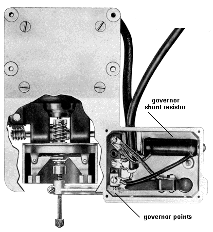
doesn't crawl with the points open and a music roll installed. Resistor
R1
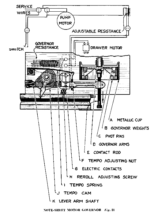
reduces the sparking across the points and also provides a current path
to the motor when the points open, which reduces motor "bumping".
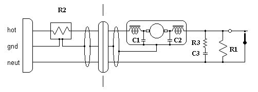
If interference to television or radio recievers occur these additional
components may be added:
1. Replace the two-conductor wire which connects the motor assembly
to the adjustable resistor with two-conductor shield wire rated for 120
vac. A small twist-lock plug and socket with a center ground pin,
similar to the original 2-conductor plug, is made by Hubbell. Connect
the shield to the motor case, and also to the metal enclosure of the adjustable
resistor.
2. Connect a disc ceramic capacitor, 0.001 ufd 1600 vdc, from
each brush holder to the motor case.
3. Connect a resistor-capacitor suppressor network, located in
the base of the motor assembly, in parallel with the points and the governor
resistor.
14 December 1999
|
 Tech
Tech
 Ampico
 spoolmotor.htm


