 Mechanical
Music Digest™ Mechanical
Music Digest™ |
| You Are Not Logged In | Login/Get New Account |
|
Please Log In. Accounts are free!
Logged In users are granted additional features including a more current version of the Archives and a simplified process for submitting articles. |
|
|
MMD
|
Organ Pressure Regulator and Tremulant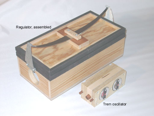 Here is a design for a small simple pressure regulator as I have finalized it after several pilot attempts, initiated by Zeb Vance who taught me about his Aeolian regulator. For my organ I have built four of these, one for each wind chest. A specific feature in this regulator type is a small balancing bellows, the interior of which is normally connected to atmosphere. A second use for this little bellows comes when you feed it with an externally supplied control pressure that will then modify the regulator output pressure. When this control is a pulse train of suitable frequency the regulator will operate as a tremulant. A particular merit of this principle, distinguishing it from conventional trems, is that it avoids power consumptive and noisy periodic air dumps. Instead the output pressure is actively controlled to pulsate. An oscillator to generate such a control signal, made from two pouch operated valves arranged into a feedback circuit is also described. This oscillator is believed to be an innovation in the art of organ building. Regulator operating principleThe output pressure of the regulator is defined by a sensing element in form of a bellows of lid area A [m2 or in2]. This lid is pushed on by a spring that delivers a force F [N or lb]. The nominal output pressure will then be P=F/A [Pa or PSI]. The lid of the bellows is connected by way of a rod to a valve disk, located below a slightly smaller hole toward the upstream unregulated pressure source. When output pressure tends to be too low, then the bellows will collapse somewhat and open up the valve disk such that flow from the unregulated input is increased. This input pressure must always be higher than the regulated output pressure. For the regulator to function over any considerable range of flows it is necessary that the area B of the valve hole/disk is not too small, it should typically be something like twice the area of the connecting trunks - this would insure the pressure loss in the regulator is in proportion to what you anyway experience in the trunks. Practically this implies that B is not very much smaller than A, so we must also account for the air pressure forces on the disk. One part of these forces is the output pressure times the disk area. Another is the unregulated input pressure that might reach the disk upstream side, tending to close it. There is also another criterion for a good regulator - the output pressure should be independent of what is this input pressure. Because of that we want the input/upstream side of the valve disk is not reached by the input pressure which might be arbitrarily high, then possibly causing a complete flow cutoff. The way to accomplish this is to put a small balancing bellows to the upstream side of the disk, vented to atmosphere, zero pressure. The effective area of this bellows should then be about the same as the valve hole area. The net effect is then that the air force, combined on the sensing bellows lid (outward) and valve disk (inward) will be F=P*(A-B), exactly balancing the spring force. This formula now tells the proper spring force to obtain a regulated pressure P. Or put the other way, P=F/(A-B). This is somewhat higher than nominal pressure above, P=F/A. We might say that the inward force on the disk helps the spring. There are also higher order effects that we may neglect in this context, like aerodynamic forces (Bernoulli effect) and the wedging effect of the bellows folds. The latter can be approximately compensated for by proper selection of the spring stiffness constant to match the bellows folds geometry.If you modulate the force on the moving armature, then the output pressure will follow. This is true irrespective of what is the air consumption rate as long as we stay within limits, essentially given by the capacity of the blower and trunking system. One may devise many methods to do this agitation for tremulant use, pneumatic, mechanic, electromagnetic, or whatever. But it appears one of the simpler is the method proposed here, to inject an intermittent control pressure into the balancing bellows, coming from the oscillator described below. When the balancing bellows is pressurized, that pressure, times the balancing bellows area, is added to the upward force on the armature. The valve then goes up (closes). The regulated output pressure drops by a corresponding amount, so that the same total upward force opposes the spring. In the present design the areas A and B relate as 9:1 suggesting that in tremulation the output pressure would oscillate between 100% (F/(A-B)) and 89% (F/A) of normal, if the control pressure is the same as the regulator output pressure. In my organ I drive the oscillator from the coarse regulated supply that is about 50% higher pressure, so the tremulation is correspondingly bigger, still perhaps quite modest. For heavier tremulation you might install an external bellows pulling the lid, possibly connected using an adjustable lever. There is always a risk with a sensitive regulator that it runs unstable and begins to oscillate on its own, in particular if it feeds a longer trunk. To cure that you can introduce some kind of damping to its armature motion - an obvious method is to decrease the diameter of the vent hole in the balancing bellows, e.g. by gluing on a piece of cardboard with a smaller hole in it. This would hardly be necessary in the tremulant application since the external tube to that bellows is an efficient aerodynamic damper in itself. Regulator construction
This drawing outlines the present design. Its body is a box, divided into an input and an output compartment. To practically accommodate intake and outlet ports of sufficient diameters the height of this box is more than strictly necessary for its internal contents of valve disk and balancing bellows plus valve travel distance, hence a space block between the disk and the balancing bellows. A valve travel of 1/4 of the valve hole diameter corresponds to full opening, any further travel capacity is of no merit. If the in and out ports are made through the bottom board the box height can be somewhat diminished. The box and bellows frames are solid wood, the bottom and top boards and the bellows lid are plywood. The top board is glued to the box frame toward the big sensor bellows. This cover has the circular valve seat and a big hole to let flow toward the output. The box bottom is a flat board where the balancing bellows is centrally mounted with a screw. The assembly is held together by eight long screws gripping Teenuts inserted into the frame of the sensor bellows, make for easy disassembly. The balancing bellows lids are plywood squares. Vent hole and centrally mounted Teenuts must be prepared before the leather/bellows cloth is glued on. There is no need for any stiffeners on the folds of this bellows, it has an inside pressure that is always lower than outside. The big sensor bellows is shaped on two wood frames. The outer one is covered by thin plywood to promote low weight and high regulator speed. Before the bellows cloth is glued on it should be prepared with cardboard stiffeners, and Teenuts installed in the inner frame. The insert shows a few variant ways to make the bellows. The left alternative with inward ribbed folds is the better one, also shown in the main drawing. The others are easier to build, but perform slightly worse - they have smaller effective bellows area and a force vs. travel characteristic that does not very well match a spring force increasing with excursion. The spring design using a leaf spring is my favorite, being compact
and simple. I made mine from 1 mm hardened steel sheet that can be
cut, even with a hand cutter (at some effort), but hardly sawn. After grinding
its edges to be smooth it is bent into a circular shape. Its rhombic surface
profile will then render the spring almost flat when maximally tensioned
as when the bellows is inflated. There are several alternate ways to arrange for a spring. A common one is to use a set of tension coil springs (mostly 4), extending between horns on the bellows lid and the box bottom board. Another is to make a bridge over the bellows and insert compression coil or compass springs in between. Apart from using up more space this is also somewhat tricky to adjust to make the bellows lid move in parallel. Yet another variation is when you make the bellows in form of a hinged wedge. Then the bellows buffering capacity is halved, but it is much easier to adjust pressure - you just move the spring attack point closer to or further away from the hinge.
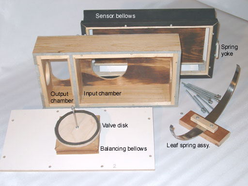
This picture shows the regulator parts after unhooking the spring and removing the connecting rod nut and bottom screws. The valve disk and the box frame have glued on leather gasket strips. Particularly important is the one on the wall between the two box chambers. If the input pressure is excessive it may happen the bottom board bulges enough to open a leak here, such that output pressure gets too high at low loads. This can be cured by an extra screw through the bottom into the separating wall. Trem oscillatorFor an oscillator you basically need an inverting valve feeding back its output to its input. To control the speed you also need a delay element. And to render a reliable start, some kind of hysteresis, otherwise the device may stay in some intermediate half open position. This is often implemented with a sliding valve element with backlash.The present primary invention is to make an inverting outside valve with its two seats unequal diameters, the left one in this drawing.
That makes for hysteresis: it takes a high pouch well pressure to press the stem down and flip its output from pressure to atmosphere. But pouch well pressure to flip the other way is significantly lower. Another formulation: Suppose the valve stem is in its up position such that the output is pressurized. We feed this output via a bleed screw back to the pouch well. Then the pressure here increases only slowly because of that narrow air passage. When the stem finally begins to move the lowest valve disk leaves its seat and we lose some little downward force. But then the supply pressure will operate on the upper valve disk. Since this one has a greater area than the lower disk the net force driving the stem down suddenly increases and the valve flips over momentarily, despite the slowness in the pouch force increase. In my first attempt I used such a valve alone, feeding its output back to the pouch well via a screw adjusted bleed. This one did oscillate, but at too high speed for tremulant usage, 20 to 30 Hz range, while you would want some 7 Hz. To get lower frequencies I had to tighten the screw to such a small bleed that operation became unreliable because of pouch leakage etc. So finally I added a non inverting amplifier valve into the feedback path, right one in the sketch. Also this one with unequal seats for hysteresis. So now there are two bleed screws that should be adjusted about in parallel. (For an overview of valve principles, in particular inverters vs. amplifiers, see http://foxtail.com/Tech/pouchvalves.html). When oscillating, the two valves flip over at interlaced instances in a four stroke pattern: left up - right down - left down - right up. With properly adjusted bleed screws these transitions should come at reasonably equal intervals. However, you can not appreciably influence the oscillator duty cycle, the relation between on and off times in the output pressure - normally you would like these times to be equal. This instead depends on that the pouch well pressures for transitions are about symmetrical around half the supply pressure, in turn a consequence of the diameter relations between pouch and valve seats. With the sizes drawn this comes out about right. The duty cycle can be modified using a weak spring pushing the right valve stem either way. For reliable operation you must put a limit to the air load at the output, e.g. by tubing it to a bellows like in the suggested application. If the output is 'short circuit', blowing directly to atmosphere, then maybe the pressure in the output cavity between the valve disks never goes high enough to operate the other valve. Also the supply must be tubed wide enough to avoid excessive pressure loss during the transition interval when neither disk in a valve makes contact with its seat. The main valve (left) has an extra control pouch at top. When this is pressurized the stem is unconditionally forced down such that the oscillator stops and its output is vented to atmosphere. That output is tubed to the vent of the balancing bellows in the chest regulator as described in the previous sections above. In my organ the control input connects to a register unit which delivers a pressure signal to turn off a rank, or presently, this oscillator. Alternatively one may connect it to e.g. a Reisner chest magnet (OSI 5501.xx series) that will then start the oscillator when energized. The device is constructed as a stack of four flat wooden pieces plus a metal plate forming the inner valve seats. The whole thing is held together by a number of long screws. Use some care to drill the many holes well aligned. The first operations would be to clamp all blocks together and draw an external oblique marker line across them. This will aid correct reorientation once the stack has been taken apart. Then drill holes for two diagonal mounting screws, install these and remove clamp. Next drill for the remaining mounting screws plus small holes to proper depth at the positions of the valve stems. These holes serve as center markers when you later drill out the bigger internal cavities - then a Forstner drill bit is preferred. All pouches are glued the 'wrong way', to the wood piece below the respective pouch in the drawing. This makes all internal parts accessible.
Johan Liljencrants 2001-12-01 |
 With
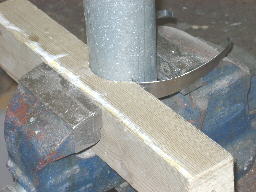
spring steel you can curve it into a radius (when relaxed) approximately
100 times the material thickness. For the shaping I used a 65 mm (2.5 in)
diameter iron tube and a wood block hollowed out to match its surface over
1/3 of its circumference. Then pressed the spring between the tube and
the block in a bench vise, at several close places along it. With two spring
leaves of the dimensions shown the regulated pressure will be about 2.5
kPa (10 inWC), when you remove the smaller leaf about 1.5 kPa. In general,
at a given spring thickness, length, and curvature, its force is proportional
to its width at the middle. To set the regulated pressure you can either
use a single leaf and try out a matching width, or you can experiment with
additional stacked leaves as shown. The middle of the spring is clamped
between two wood strips that rest on the lid. They stabilize the spring
and prevent it from tipping sideways. They are held by the spring force
and a hole enclosing the end of the connecting rod between lid and valve
disk.
With
spring steel you can curve it into a radius (when relaxed) approximately
100 times the material thickness. For the shaping I used a 65 mm (2.5 in)
diameter iron tube and a wood block hollowed out to match its surface over
1/3 of its circumference. Then pressed the spring between the tube and
the block in a bench vise, at several close places along it. With two spring
leaves of the dimensions shown the regulated pressure will be about 2.5
kPa (10 inWC), when you remove the smaller leaf about 1.5 kPa. In general,
at a given spring thickness, length, and curvature, its force is proportional
to its width at the middle. To set the regulated pressure you can either
use a single leaf and try out a matching width, or you can experiment with
additional stacked leaves as shown. The middle of the spring is clamped
between two wood strips that rest on the lid. They stabilize the spring
and prevent it from tipping sideways. They are held by the spring force
and a hole enclosing the end of the connecting rod between lid and valve
disk.
|
|
|
|
|
|
|
|
|
CONTACT FORM: Click HERE to write to the editor, or to post a message about Mechanical Musical Instruments to the MMD Unless otherwise noted, all opinions are those of the individual authors and may not represent those of the editors. Compilation copyright 1995-2026 by Jody Kravitz. Please read our Republication Policy before copying information from or creating links to this web site. Click HERE to contact the webmaster regarding problems with the website. |
|
|
||||||
|