Chapter 6 - Assembling the Lower Units
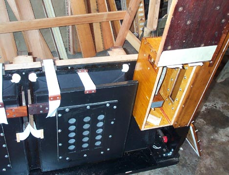
Now that the pumping unit and the two stop chests are complete, these units are assembled. The stop chests are attached to the pumping unit end supports, and also screwed and gasketed to the reservoir, using the bass spottiest as an "elbow" at the bass end, and the smaller treble end "elbow" (not shown) at the treble end. Because there are gasketed faces on two planes, there has to be a means to assure that both joints are drawn up equally. The screw holes in both faces of the elbows are enlarged to allow free movement in both directions, and the screws are drawn tight a little at a time, alternating between the back and side joints.
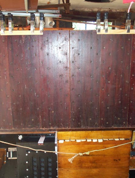
The six backplane panels are prepared for temporary installation. The vertical channels in them go all the way from end to end, and the open ends of the channels are covered with cloth, which was replaced. The lower ends of the channels for the first 13 bass notes, in the leftmost two boards, connect to the bass chest spreader board, so holes are punched in the cloth ends for these notes. One of the backplane panels was cracked on one edge, probably due to distortion of the whole case, when the organ was moved without all the components being firmly screwed together. This was mended with shellac and screws.
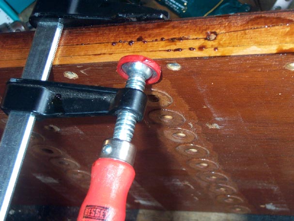
The problem here is to get everything put together so that the six backplane panels are perfectly vertical, parallel, and spaced crosswise such that the width of the gap between the spottiest just fits the rank chests that will go in there. The rank chests should slip easily into place, with no strain on them, with all the holes in the backplane lined up on a perfectly flat plane. There are dowels in the outermost backplane panels that fit into holes at the ends of each rank chest; the chest should slip onto these pins without forcing. Since the entire basic structure was taken apart, and there are bound to be dimensional changes in the wood due to the passage of time, the reassembly must be done in a way that reestablishes the key dimensions around the rank chest area. After initial assembly, this gap was found to be too wide, so all the screws joining the spottiest, elbows, and reservoir were loosened, and the gap pulled in, using a rank chest back board as a guide. Note that the bass chest was also installed, since its top spreader board is the only thing that holds the three bass end backplane boards in position.
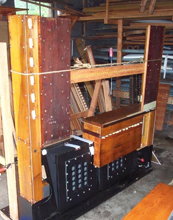
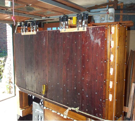
Now the wooden strip that supports the three treble end panels is installed, and the remaining four backplane panels are attached to it, or the bass chest top. A new center support leg is made. (This also holds up the bass chest resonator box, along with another short support leg shown at the right.)
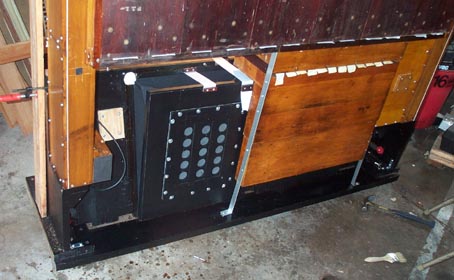
Here you can see that the center gap between the third and fourth panel is too wide at the top, showing that the support leg is too long, pushing the middle of the assembly too high. The leg length is adjusted to make this right. The three panels on each side are clipped together temporarily, just to hold them in place. Except for the two outermost panels, there is nothing to hold them upright except the screws on their bottom edges.