Chapter 18.5 - Assembling the Secondary
The cover plate, as well as all the blocks that form the ends of the wind passage, are gasketed with L. S. H. split, just like the valve side of the back board, and the box is assembled without the pouch board.
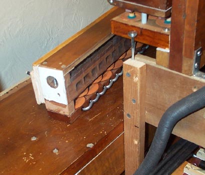
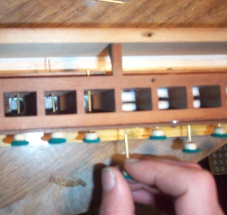
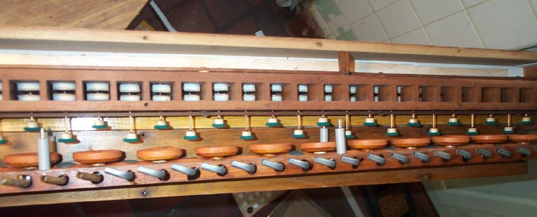
Aeolian developed a clever way to make it easy to install the valve disks on the stem wires, in the confined space of the valve cells. The cells do not go all the way through the valve body, but are milled out with a varying cross section. When two disks are dropped in, they end up resting on the bottom of the wider part. Their location is such that when the stem wire is poked through the lower guide at a slight downward angle, the narrow, smooth end of the wire neatly stabs the pre punched valve center holes
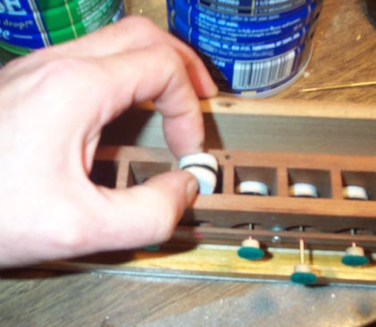
First reach in the cell with one finger to hold both disks from turning, and spin the stem button. Turn until some resistance is felt, indicating that the threaded part of the stem is engaged with the cowhide layers near the middle of the two disks. No picture here, because this takes two hands, leaving none to hold the camera. Now keep turning, while pulling on the button. This holds the lower disk against the lower seat, keeping it from turning. Then the wire keeps on screwing upward, through the lower disk, but carrying the upper disk (free to turn with the wire) towards the upper seat. As the point of the wire emerges from the upper valve hole, make sure the wire is held parallel to the axis of its final motion, and aim the point towards the bushed hole in the inner stem guide. One has to be careful here, looking at the situation from different angles, with a strong light. The screwing action can easily poke out the bushing or bend the guide strip up, unless the wire point goes right into the bushing hole.
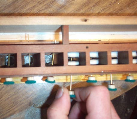
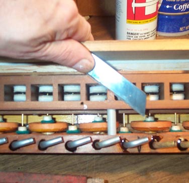
Soon the upper disk fetches up against the upper seat hole. Then it also stops turning freely with the wire; now both disks are "trapped" inside the valve cell and won't turn. The the wire can be screwed up or down, to establish its preliminary position, judged by looking at how much the point protrudes above the inner stem guide. Now the final position of the disks can be accurately established. If the button is pushed hard and turned, the lower disk is freed but the upper disk is held by friction, and can be moved on the wire by screwing. Likewise, if one pulls and turns, only the lower disk can be moved on the wire. I left the settings at this stage as follows: When the valve is in the down position, the tip of the wire poked about 1/16" above the upper guide bushing; and a gap of about 3/32" was left between the disks. This sounds more complicated than it actually is; only a few turns of the button are needed to get it right. I'll bet that the poor immigrant girls who did this for a living at 12-1/2 cents an hour in New Jersey, did this so many times that they got the positions right with the first poke-and-turn.
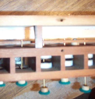
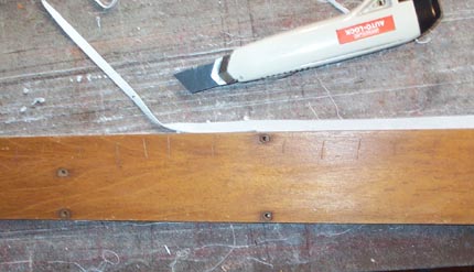
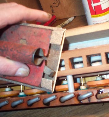
At this point I noticed that the end blocks of the assembly poked out a little bit. Apparently the longitudinal boards comprising the assembly had shrunk in width from age, but the end blocks, with their grain at right angles to the boards, had not. Wood only shrinks across its width, not longitudinally. So the back board had to come off, and the end blocks shortened with a few strokes of sandpaper.
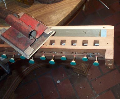
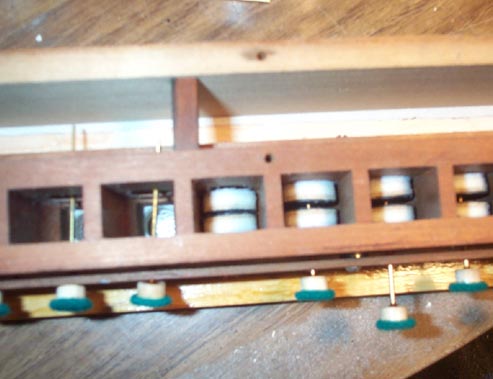
The pouch board is now attached, with new spacers to replace the old ones that were split or lost.
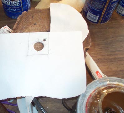
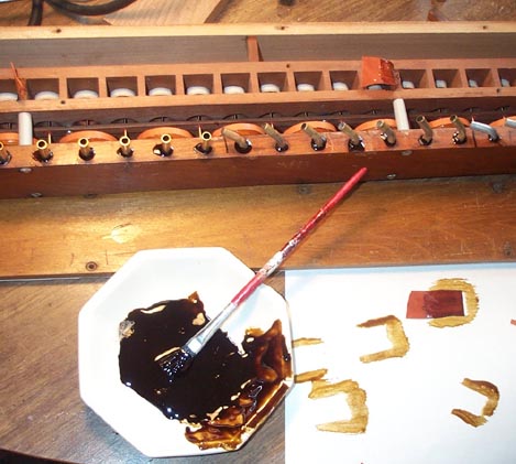
The screws holding the pouchboard had caused a few of the barriers between the valve cells to split a little, leaving a potential leak between the cells. Like the barriers between the reed cells on a vacuum organ, they are milled across the grain, and are very delicate. At all the spacers, cracked or not, I patched the leak area with pouch leather. Since the cell walls were shellacked to seal against internal leakage, the patches were attached with thick shellac, not glue. Aeolian often used such patches on the sides of closely spaced channels of pipe organ valve boards.
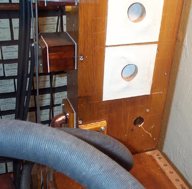
The secondary valve assembly is mounted in the organ, between the two stop chests, under the lowest reed rank. But, unlike the reed chests, there is no "self energizing" gasket for this connection. But the distance between the stop chests is fixed by the structure of the instrument. There is no way to "pull up" this gasketed joint, since the stop chests won't move. It is necessary to use gaskets (there is a wind hole at both ends) that will be snug of their own accord. Gaskets made of L. S. H. thick elk skin fit the bill here. (At final assembly, I smeared them with Dow-111, for additional leak tightness. It is also greasy, and made the piece slide into place easier. Note another clever detail. There is only one screw at this joint, just to keep the secondary up in its correct place. The assembly can turn slightly around this screw, so that when the back plane panels are screwed to the back of the assembly, it will align itself squarely to the surface of the back panels.