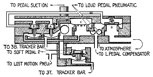
Two pouches C and D are employed to operate the loud pedal pneumatic: C to admit suction to collapse it, and D to admit atmosphere to open it.
Suction pouch C is operated by an inside primary valve A which is controlled from the 3B hole [Loud Pedal] in the tracker bar.
The atmosphere pouch D is operated by an inside primary valve B which is controlled by the primary valve A.
The pouch C and its primary valve A are supplied with suction from the pedal regulator.
Pouch D and its primary valve A are supplied with suction, temporarily generated by the pedal pneumatic as it opens.
When the 3B tracker hole is opened, the primary valve A raises and admits suction to the pouch C, which in turn raises from its seat and admits suction to the pedal pneumatic.
This suction, aided by a spring, holds pouch D against its seat, thereby sealing the atmosphere passage to the pneumatic.
When the pneumatic is fully closed, the suction in the chamber under the pouch C becomes the same as that above it, and the pouch is in balance.
The suction in the pneumatic now supplies the pouch chamber of valve B, but as its pouch is balanced by the suction from valve A, which is up, the valve B remains down.
When the tracker hole 3B is closed, the valve A drops and admits atmosphere to the pouch C, thereby pressing it against its seat and cutting off suction to the pneumatic.
At the same time, atmosphere from the valve A
is admitted to the under side of the pouch of valve B, and suction
generated by the pedal pneumatic as it opens raises the valve B.
This admits generated suction to the pouch D, which lifts from its
seat and admits atmosphere to the pneumatic which opens.
During the time that the pneumatic opens, it generates
suction which holds the pouch D away from its seat. However,
as soon as the pneumatic is fully opened, it ceases to generate suction
and the valve B and pouch D return to their seats.
The valves are now in position for the next perforation
in the note sheet.
Constrictions are placed in the tubes leading to
pouches C and D to control their speed of operation.
This mechanism has been designed to obtain rapid
and quiet damper operation.
The dampers should be adjusted so that when they
are raised the strings are fully cleared by the wedge-shaped dampers.
This adjustment is made by a stop screw in the moveable
board of the pneumatic.
Reproduced from page 27,
The Ampico Service Manual 1929,
Copyright 1929 by American Piano Company